Rotating shuttle anti-lock mechanism

A technology of shuttle guard and rotary hook frame, which is applied in the direction of sewing machine collar mechanism, sewing machine components, sewing machine control device, etc., can solve the problems affecting work efficiency and cumbersome operation, so as to improve production efficiency, avoid impact and reduce damage. Effect of chance of getting stuck

Active Publication Date: 2022-06-03
NINGBO YINZHOU YONGYAO SEWING MACHINERY
View PDF9 Cites 0 Cited by
  • Summary
  • Abstract
  • Description
  • Claims
  • Application Information

AI Technical Summary

Problems solved by technology

[0004] In view of the related technologies mentioned above, the inventor believes that there are the following defects: after the rotary hook is stuck, it is necessary to disassemble the rotary hook and take out the thread body before the sewing machine can work normally, and the operation is cumbersome, which affects work efficiency

Method used


Image

  • Rotating shuttle anti-lock mechanism
  • Rotating shuttle anti-lock mechanism

Examples


Embodiment Construction

[0026] The present application will be further described in detail below with reference to the accompanying drawings.

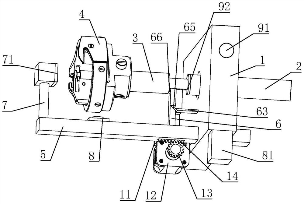
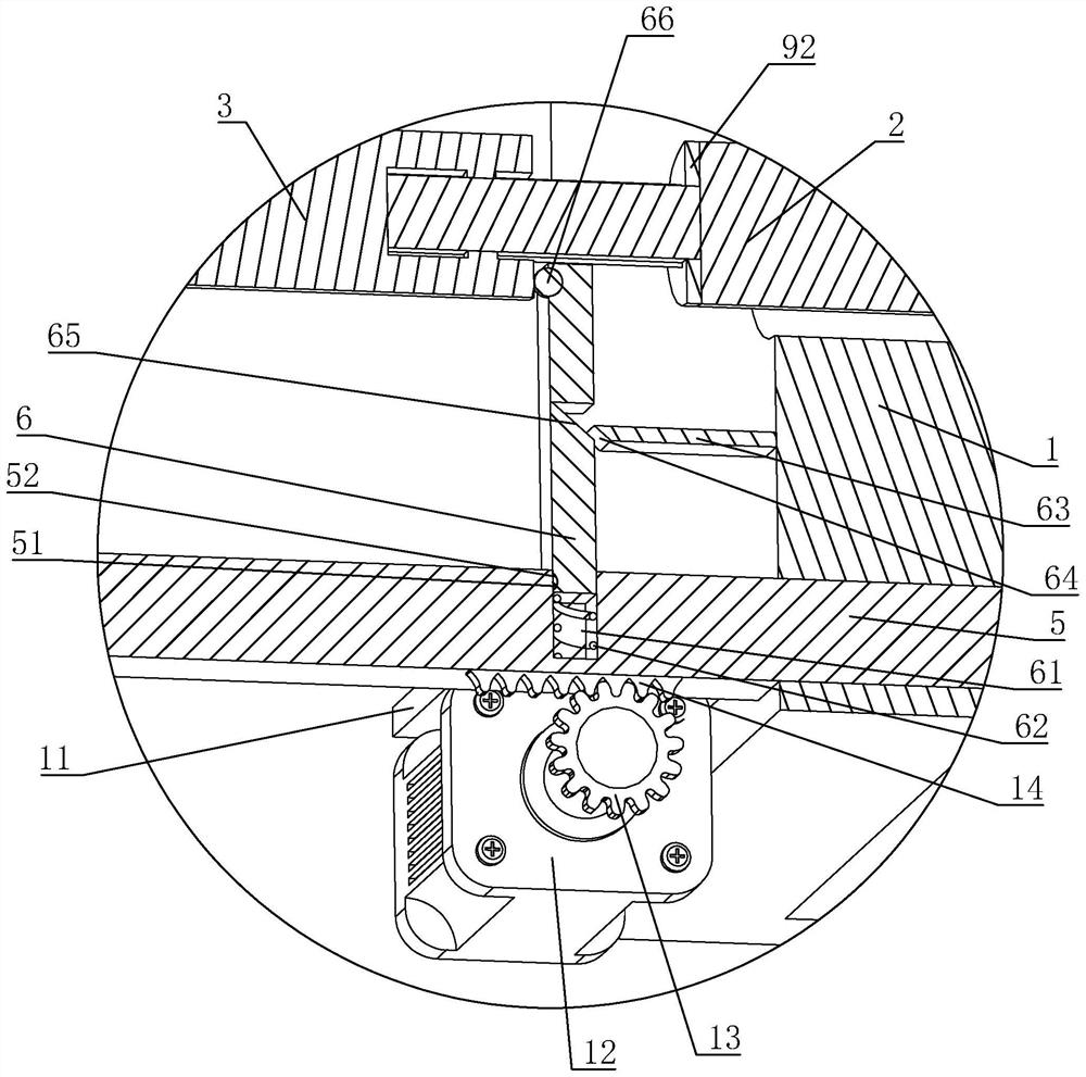
[0027] This embodiment: a rotary hook anti-lock mechanism, refer to figure 1 and figure 2 , including: a rotary hook frame 1 and a first rotary shaft 2 rotatably connected to the rotary hook frame 1 through a bearing, the end of the first rotary shaft 2 is slidably connected with a second rotary shaft 3 along the extension direction of the first rotary shaft 2, and the end of the first rotary shaft 2 is slidably connected The second shaft 3 is provided with a guide groove for sliding, the end of the second shaft 3 away from the first shaft 2 is installed with a rotary hook 4, and the sewing machine is installed with a clutch motor for driving the first shaft 2 to rotate.

[0028] When the sewing machine is working, the clutch motor drives the first rotating shaft 2 to rotate at a constant speed, the first rotating shaft 2 drives the second rotating shaft 3 ...


PUM


Abstract

The invention relates to a rotating shuttle anti-lock mechanism, and belongs to the field of electric sewing machines, the rotating shuttle anti-lock mechanism comprises a rotating shuttle frame and a first rotating shaft rotationally connected to the rotating shuttle frame, the end part of the first rotating shaft is slidably connected with a second rotating shaft, and the second rotating shaft is provided with a rotating shuttle; the rotating shuttle frame is slidably connected with a supporting rod, the rotating shuttle frame is provided with a driving mechanism used for driving the supporting rod to slide, the supporting rod is connected with a pressing rod used for abutting against the end face of the side, away from the rotating shuttle, of the second rotating shaft, the supporting rod is connected with a push rod used for pushing the rotating shuttle to move, and the supporting rod is provided with a rotating speed sensor used for detecting the rotating speed of the rotating shuttle. During use, when the rotating speed sensor detects that the rotating speed of the rotating shuttle is reduced, the push rod pushes the rotating shuttle to move, so that a shuttle tip on the rotating shuttle and a machine needle are staggered, the rotating shuttle is prevented from continuously clamping a thread, the possibility that the rotating shuttle is clamped is reduced, and the rotating shuttle is prevented from being damaged. And the thread body in the rotating shuttle can be continuously used after being drawn out and the rotating shuttle is reset, so that time and labor are saved.

Description

technical field [0001] The present application relates to the field of electric sewing machines, in particular to an anti-lock mechanism of a rotary hook. Background technique [0002] The rotary hook is an important component of the sewing machine. The rotary hook includes an inner shuttle and an outer shuttle that is rotatably connected to the outer track of the inner shuttle. A bobbin case is clamped on the rotating shaft of the inner shuttle, and a bottom thread is wound in the bobbin casing. [0003] Before using the sewing machine, it is necessary to install the outer shuttle on the shuttle shaft of the sewing machine, the hook tip on the outer shuttle is located directly under the needle, and the shuttle bar of the sewing machine is inserted into the groove on the inner shuttle to limit the inner shuttle. , the clutch motor drives the outer shuttle to rotate at a constant speed through the shuttle shaft, the shuttle tip on the outer shuttle hooks the thread loop at th...

Claims


Application Information

Patent Timeline
Patent Type & Authority Applications(China)
IPC IPC(8): D05B57/38D05B69/30
CPCD05B57/38D05B69/30
Inventor 汪小勇李刚
Owner NINGBO YINZHOU YONGYAO SEWING MACHINERY
Why Eureka
Try Eureka