
Pay-off frame for flight stringing

A pay-off frame and stringing technology, applied in the field of pay-off racks, can solve problems such as unsuitable construction parties, increased weight, and complex structures, and achieve the effects of light overall weight, simple connection devices, and accurate flight routes

Active Publication Date: 2016-01-13
STATE GRID CORP OF CHINA +2
View PDF6 Cites 0 Cited by
  • Summary
  • Abstract
  • Description
  • Claims
  • Application Information

AI Technical Summary

Problems solved by technology

However, this stringing device has a complicated structure and inevitably increases weight, so it also needs to use a large aircraft such as a helicopter to complete it.
However, the cost of using a large aircraft can easily reach hundreds of thousands or even millions of yuan, which is not suitable for the construction party in terms of economic benefits and work efficiency.

Method used


Image

  • Pay-off frame for flight stringing
  • Pay-off frame for flight stringing
  • Pay-off frame for flight stringing

Examples


Embodiment Construction

[0021] The present invention will be described in further detail below in conjunction with the accompanying drawings.

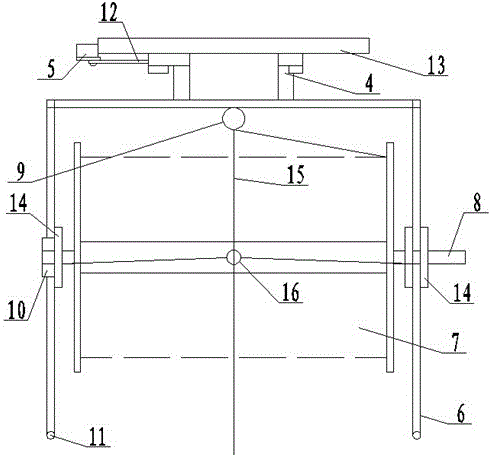
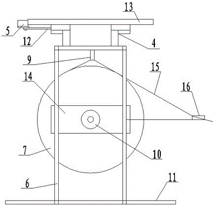
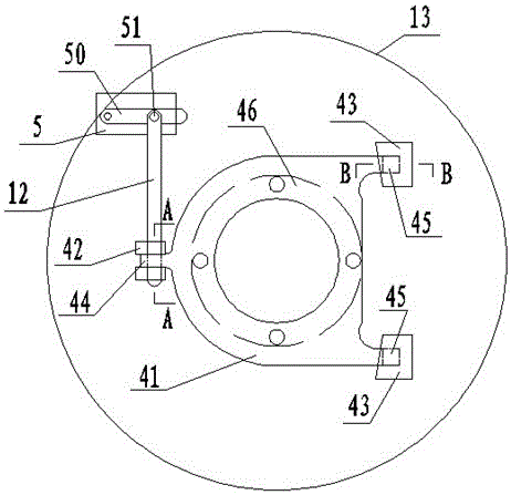
[0022] Such as figure 1 , 2 As shown, the main body of the pay-off frame for aerial stringing of the present invention is a frame made of light and high-strength pipes (such as carbon pipes), and a bobbin 7 is installed in the frame, and a Dyneema rope 15 is wound around the bobbin 7 . The aircraft may be a multi-axis multi-rotor aircraft. The aircraft chassis 13 is provided with a control device for controlling the flight of the aircraft. The control device can receive the signal from the remote control device to control the flight of the aircraft, and can also realize the automatic flight control of the aircraft according to the signal of the navigator.

[0023] The following of the aircraft chassis 13 is connected to the pay-off rack 6 through a connecting device 4, so that the pay-off rack 6 can rotate freely and can be separated from the aircraft chass...


PUM


Abstract

The invention discloses a pay-off rack for flight stringing. The upper portion of the pay-off rack is connected with a chassis of an aircraft through a connecting device. The pay-off rack is a framework which is provided with an underframe at the bottom end and is made of light high-strength tubes. The pay-off rack at one end of a wire shaft is provided with a damper. The connecting device comprises a socket fixed on the chassis of the aircraft and a connecting plate with a plug. The plug of the connecting plate is inserted in the socket of the chassis of the aircraft in a matching mode. The connecting plate is connected with the top end of the pay-off rack and can rotate relative to the top end of the pay-off rack. The chassis of the aircraft is further provided with a drive mechanism capable of separating the plug from the socket. The pay-off rack of the flight stringing is light in weight, accurate in paying off wires, capable of flying a long distance, and capable of automatically separating the aircraft from the pay-off rack.

Description

technical field [0001] The invention relates to a device for using an aircraft to pull and pay out wires during the wiring process of a power transmission line, in particular to a wire payout frame. Background technique [0002] In the process of erecting transmission lines, it is necessary to erect heavy conductors on iron towers. At this time, the erection method is generally to pass very light and thin Dyneema ropes through each iron tower, and then connect thicker and stronger wires. Higher Dyneema rope, and then connect the wire with a wire rope, it is best to pull the wire to the iron tower through the tractor. When erecting long-distance power transmission lines, because the distance is as long as several kilometers or even tens of kilometers, aircrafts such as model airplanes are generally used for traction when placing the first Dyneema rope. Such as publication number is 10806091 Chinese patent literature, just provides a kind of electric helicopter, is to be inst...

Claims


Application Information

Patent Timeline
Patent Type & Authority Patents(China)
IPC IPC(8): H02G1/02B65H49/18
Inventor 董树森李新周雪涛高笑茶盖志军郭珊张哲万冀杰张湘潭尹泉军王文义
Owner STATE GRID CORP OF CHINA
Learn More