Cutter wear monitoring method based on physical information fusion

A technology of tool wear and physical information, applied in manufacturing tools, measuring/indicating equipment, metal processing equipment, etc., to achieve the effect of reducing economic losses, low prediction errors, and reducing model complexity

Active Publication Date: 2022-05-31
HEFEI INSTITUTES OF PHYSICAL SCIENCE - CHINESE ACAD OF SCI
View PDF6 Cites 2 Cited by
  • Summary
  • Abstract
  • Description
  • Claims
  • Application Information

AI Technical Summary

Problems solved by technology

[0004] The present invention aims to solve the deficiencies of physical models and data-driven models in tool wear monitoring, and proposes a tool wear monitoring method based on physical information fusion with small errors, good real-time performance, and easy deployment, in order to be able to perform in unknown working conditions Stable and accurate monitoring of tool wear, so as to compensate for machining errors and reduce losses caused by excessive tool wear

Method used


Image

  • Cutter wear monitoring method based on physical information fusion
  • Cutter wear monitoring method based on physical information fusion
  • Cutter wear monitoring method based on physical information fusion

Examples


Embodiment Construction

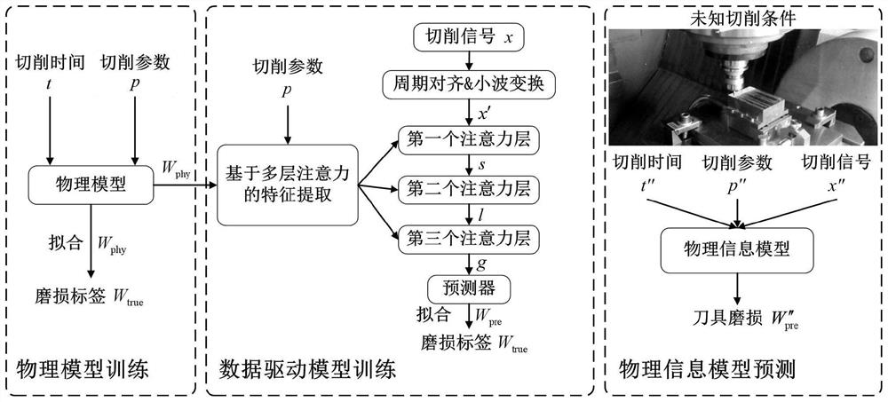
[0036] In this embodiment, a tool wear monitoring method based on physical information fusion combines a physical model and a data-driven model to realize real-time high-precision tool wear monitoring, including: CNC machine tools, force sensors, industrial computers, and physical information algorithms:

[0037] In this embodiment, the CNC machine tool adopts the high-speed milling machining center Mikron HSM600U, which includes a bus interface and a sensor bracket, the force sensor is installed on the sensor bracket, and the milling cutters used are all three-blade milling cutters. The workpiece adopts AISI4340 square die. The workpiece was rough-milled before the experiment to ensure the flatness of the workpiece. The workpiece surface is cut in a zigzag shape by the tool from the upper edge to the lower edge. After each transverse cut, the wear of both edges was measured by a LEICAMZ12 microscope. During the processing of the workpiece, the cutting force signal is obtain...


PUM


Abstract

The invention discloses a cutter wear monitoring method based on physical information fusion, which can accurately diagnose and predict the current cutter wear state in the machining process and prompt a machining system to replace a cutter in time. The method comprises the following steps: 1, collecting processing information and constructing a training data set; 2, constructing and training a physical model; 3, designing a pyramid data driving model based on the frequency spectrum of the cutting signal; 4, a physical information model is constructed and trained, and physical information is introduced through a multi-layer attention mechanism to guide feature extraction of the model; and 5, monitoring tool wear by using the trained physical information model. The tool wear can be monitored stably and accurately under the unknown working condition, so that the machining error is compensated, and the loss caused by over-wear of the tool is reduced.

Description

technical field [0001] The invention relates to the field of tool wear monitoring, in particular to a tool wear monitoring method based on physical information fusion. Background technique [0002] In recent years, with the development of technology, the complexity and precision of processing have been greatly improved. The health of the tool directly affects the quality of the milling process and the product. To ensure machining accuracy, machining reliability and personnel safety, tool wear needs to be monitored during the milling process. Although the related tool wear monitoring research has been very extensive, the existing models can only achieve excellent performance under known machining conditions, but cannot be generalized to other machining scenarios, so the existing research results still cannot be applied to actual machining. in the process. [0003] According to different theoretical foundations, tool wear models are roughly divided into physical models and ...

Claims


Application Information

Patent Timeline
Patent Type & Authority Applications(China)
IPC IPC(8): B23Q17/09
CPCB23Q17/0957Y02P90/02
Inventor 朱锟鹏郭浩
Owner HEFEI INSTITUTES OF PHYSICAL SCIENCE - CHINESE ACAD OF SCI
Why Eureka
Try Eureka