Efficient heat dissipation device of CT (Computed Tomography) diagnostic equipment

A diagnostic equipment and heat dissipation device technology, which is applied in the direction of radiological diagnostic instruments, diagnostics, electrical equipment components, etc., can solve the problems of inability to dissipate heat from CT diagnostic equipment, limited heat dissipation area, and low efficiency

Inactive Publication Date: 2022-05-27
淄博市淄川区中医院
View PDF1 Cites 0 Cited by
  • Summary
  • Abstract
  • Description
  • Claims
  • Application Information

AI Technical Summary

Problems solved by technology

[0006] According to the Chinese patent disclosed by the patent No. CN212415756U, the device can only blow and dissipate heat at a fixed angle of the CT diagnostic equipment, resulting in a limited area of ​​heat dissipation and low efficiency, and cannot quickly dissipate heat from the CT diagnostic equipment.

Method used


Image

  • Efficient heat dissipation device of CT (Computed Tomography) diagnostic equipment
  • Efficient heat dissipation device of CT (Computed Tomography) diagnostic equipment
  • Efficient heat dissipation device of CT (Computed Tomography) diagnostic equipment

Examples


Embodiment 1

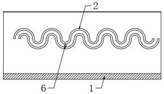
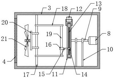
[0026] like Figure 1 to Figure 4 As shown in the figure, a high-efficiency heat dissipation device for CT diagnostic equipment proposed by the present invention includes an outer casing 1 of a CT diagnosis equipment, and a cooling bellows 3 is slidably connected to the inner side of the outer casing 1 of the CT diagnosis equipment, and the outer side of the cooling bellows 3 is installed There is a cleaning mechanism for cleaning dust, an angle adjustment mechanism is installed on the inner side, and a ventilation net 4 for dust is installed at the opening of the cooling bellows 3, and a cooling fan 21 is installed on the angle adjustment mechanism. On one side of the net 4, the cleaning mechanism includes a wave guide rail 2 fixed on the inner side of the outer casing 1 of the CT diagnostic equipment and a brush connecting arm 5 rotatably connected with the cooling air box 3, and the two brush connecting arms 5 are connected with cleaning soft The brush 7, and the brush conn...

Embodiment 2

[0029] like Figure 1-4 As shown in the figure, a high-efficiency heat dissipation device for CT diagnostic equipment proposed by the present invention, compared with the first embodiment, this embodiment also includes a cooling bellows 3 slidably connected to the inner side of the outer casing 1 of the CT diagnostic equipment, and the cooling bellows 3 is A cleaning mechanism for cleaning dust is installed on the outside, an angle adjustment mechanism is installed on the inside, and a ventilation net 4 for dust prevention is installed at the opening of the cooling air box 3, and a cooling fan 21 is installed on the angle adjustment mechanism. The cooling fan 21 Located on one side of the ventilation net 4, the cleaning mechanism includes a wave guide rail 2 fixed on the inner side of the outer casing 1 of the CT diagnostic equipment and a brush connecting arm 5 rotatably connected with the cooling air box 3. The two brush connecting arms 5 are connected with Clean the soft br...


PUM


Abstract

The invention relates to the technical field of medical equipment, in particular to an efficient heat dissipation device of CT diagnosis equipment. In order to solve the problems that an existing heat dissipation device is limited in heat dissipation range and not high in efficiency on the CT diagnosis equipment, the technical scheme includes that the CT diagnosis equipment heat dissipation device comprises a CT diagnosis equipment outer shell, a heat dissipation air bellow is slidably connected to the inner side of the CT diagnosis equipment outer shell, a cleaning mechanism used for cleaning dust is installed on the outer side of the heat dissipation air bellow, and an angle adjusting mechanism is installed on the inner side of the heat dissipation air bellow; a heat dissipation air bellow is installed on the outer shell, a dustproof ventilation net is installed at an opening of the heat dissipation air bellow, a heat dissipation fan is installed on the angle adjusting mechanism and located on one side of the ventilation net, and the cleaning mechanism comprises a wave guide rail fixed to the inner side of the outer shell of the CT diagnostic equipment and a brush connecting arm rotationally connected with the heat dissipation air bellow. And the two brush connecting arms are connected with a cleaning soft brush. The angle of the cooling fan can be automatically adjusted, and the swing amplitude can be adjusted at will, so that the high temperature of the CT diagnosis equipment can be quickly dissipated.

Description

technical field [0001] The invention relates to the technical field of medical equipment, in particular to an efficient heat dissipation device for CT diagnostic equipment. Background technique [0002] CT scans a layer of a certain thickness of a certain part of the human body with an X-ray beam. The detector receives the X-rays that pass through the layer, converts them into visible light, and converts them from photoelectricity to electrical signals, which are then converted by an analog / digital converter. For numbers, input computer processing. The processing of image formation is like dividing the selected slice into several cuboids with the same volume, which are called voxels. [0003] The information obtained by scanning is calculated to obtain the X-ray attenuation coefficient or absorption coefficient of each voxel, and then arranged into a matrix, that is, a digital matrix, and the digital matrix can be stored in a magnetic disk or an optical disk. Through the d...

Claims


Application Information

Patent Timeline
Patent Type & Authority Applications(China)
IPC IPC(8): H05K7/20B08B1/00A61B6/00
CPCH05K7/20172H05K7/20209A61B6/4488B08B1/12
Inventor 孙慧
Owner 淄博市淄川区中医院
Why Eureka
Try Eureka