
Underwater wireless charging system suitable for electric ship

A wireless charging and electric ship technology, applied in electric vehicle charging technology, charging stations, electric vehicles, etc., can solve the problems of electromagnetic interference of electronic equipment, affecting the normal operation of equipment, and reducing transmission efficiency, achieving excellent concealment and operation. Simple and safe and reliable, the effect of small power fluctuations

Pending Publication Date: 2022-05-27
NINGBO POWER SUPPLY COMPANY STATE GRID ZHEJIANG ELECTRIC POWER +1
View PDF0 Cites 0 Cited by
  • Summary
  • Abstract
  • Description
  • Claims
  • Application Information

AI Technical Summary

Problems solved by technology

The current wireless energy transmission method mainly uses the magnetic field as the energy transmission medium. The inductance coil converts electrical energy into magnetic energy and transmits it from the transmitting end to the receiving end, and then converts it into electrical energy to charge the battery. However, its transmission efficiency is easily affected by the following two aspects : When the transmitting end and the receiving end are misaligned, the transmission efficiency will drop; the magnetic field will generate eddy current loss around the coupling mechanism, resulting in a drop in transmission efficiency
In addition, the divergent magnetic field is likely to cause electromagnetic interference to the electronic equipment on the unmanned ship, affecting the normal operation of the equipment and even causing the equipment to fail

Method used


Image

  • Underwater wireless charging system suitable for electric ship
  • Underwater wireless charging system suitable for electric ship
  • Underwater wireless charging system suitable for electric ship

Examples


Embodiment Construction

[0024] The technical solutions in the embodiments of the present invention will be clearly and completely described below with reference to the accompanying drawings in the embodiments of the present invention. Obviously, the described embodiments are only a part of the embodiments of the present invention, rather than all the embodiments. Based on the embodiments of the present invention, all other embodiments obtained by those of ordinary skill in the art without creative efforts shall fall within the protection scope of the present invention.

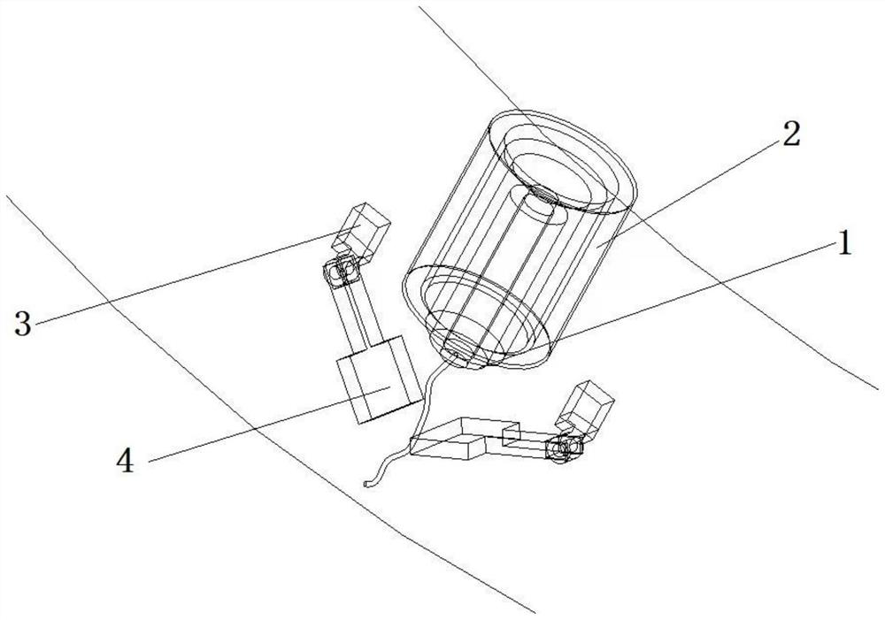
[0025] The present invention provides an underwater wireless charging system suitable for electric ships, such as Figure 1-4 As shown, it includes a receiving cylinder 2 and a launching cylinder 1, the launching cylinder 1 is connected to the onshore power supply, and the launching cylinder 1 includes a shaft body, a first steel frame 11, a first magnetic core 12, and a transmitting coil 13. The main body of the transmitting cylinde...


PUM


Abstract

An underwater wireless charging system suitable for an electric ship comprises a receiving cylinder and a transmitting cylinder, the transmitting cylinder is connected with an ashore power supply, the transmitting cylinder comprises a shaft body, a first steel frame, first magnetic cores and a transmitting coil, the transmitting coil is wound on the shaft body, the first magnetic cores are arranged at the positions, located at the two ends of the transmitting coil, of the cylinder body, and the transmitting coil is wound on the first steel frame. The first steel frame is fixed outside the barrel body and used for fixing the barrel body, the receiving barrel comprises a barrel body, a second steel frame, second magnetic cores and receiving coils, the receiving barrel is fixed on a ship body through the second steel frame, the second coils are of tubular structures and are arranged in the barrel body, the second magnetic cores are arranged in the barrel body and located at the two ends of the second magnetic cores, and the receiving coils are arranged in the barrel body. When the transmitting cylinder is inserted into the receiving cylinder, wireless charging is achieved, at the moment, the transmitting coil and the receiving coil are of a coaxial spiral tube structure, and the first magnetic core corresponds to the second magnetic core in position. According to the invention, automatic charging operation can be realized, and the charging efficiency and the safety are greatly improved.

Description

technical field [0001] The invention belongs to the technical field of wireless charging of ships, in particular to an underwater wireless charging system suitable for electric ships. Background technique [0002] In ship shipping, because ships on inland waterways and coastal routes are closer to cities, the pollution to cities is also more obvious. With the rise of wireless charging of drones and wireless charging of electric vehicles, electric ships have also begun to attract more and more people's attention. Electric ships powered by electric energy will not produce pollutants during the driving process, accompanied by environmental problems. increasingly prominent, the power source of ships is gradually developing from fossil energy to electricity. At present, domestic electric ships are mainly used in the environmental field, and now they are gradually moving towards the military field, and the future development potential is huge. However, due to the limited battery...

Claims


Application Information

Patent Timeline
Patent Type & Authority Applications(China)
IPC IPC(8): H02J50/10H02J50/90H02J50/00B60L53/12B60L53/34
CPCH02J50/10H02J50/90H02J50/005B60L53/12B60L53/34Y02T90/14
Inventor 王激华凌荣光胡海王汉丰何磊杰彭佳吴刚许巍沈寅星乐璟黎杨跃平叶佳青张伟红卓露珊左志平李小飞
Owner NINGBO POWER SUPPLY COMPANY STATE GRID ZHEJIANG ELECTRIC POWER
Learn More