
Damping vibration attenuation device and aero-engine

A vibration reduction device and damping technology, which is applied in the cooling of engine components, machines/engines, engines, etc., can solve problems such as forced response, and achieve the effect of suppressing vibration response and suppressing harmful vibration

Pending Publication Date: 2022-05-27
AECC COMML AIRCRAFT ENGINE CO LTD
View PDF0 Cites 0 Cited by
  • Summary
  • Abstract
  • Description
  • Claims
  • Application Information

AI Technical Summary

Problems solved by technology

[0003] The inventors have found that at least the following problems exist in the prior art: the structure of the vortex reducer is a multi-tube structure supported by a cantilever, which is easily subjected to the excitation of the cooling air flow in the disk cavity and thus a forced response occurs

Method used


Image

  • Damping vibration attenuation device and aero-engine
  • Damping vibration attenuation device and aero-engine
  • Damping vibration attenuation device and aero-engine

Examples


Embodiment Construction

[0023] Combine below Figure 1 to Figure 4 The technical solutions provided by the present invention are described in more detail.

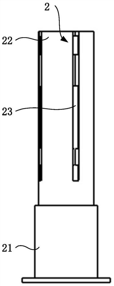
[0024] see figure 1 , the embodiment of the present invention provides a damping and vibration reduction device, which includes a vortex reducing tube 1 and a damping tube 2 . The vortex reducer 1 has a cavity 11 . The damping tube 2 is installed in the cavity 11 ; the first end 21 of the damping tube 2 is detachably connected to the top of the cavity 11 and the connection length is adjustable, and the second end 22 of the damping tube 2 abuts against the bottom of the cavity 11 , The middle portion of the damping tube 2 is configured to be deformable, and the middle portion of the damping tube 2 in the deformed state is in contact with the inner wall of the cavity 11 . The larger the deformation of the middle portion of the damping tube 2 is, the larger the contact area between the middle portion of the damping tube 2 and the inner wall of th...


PUM


Abstract

The invention discloses a damping vibration attenuation device and an aero-engine, relates to the field of aero-engines, and aims to optimize the performance of the damping vibration attenuation device. The damping vibration attenuation device comprises a vortex reduction pipe and a damping pipe. The vortex reducing tube is provided with a concave cavity. The damping tube is mounted in the concave cavity; the first end of the damping tube is detachably connected with the top of the concave cavity, the connecting length can be adjusted, the second end of the damping tube abuts against the bottom of the concave cavity, the middle of the damping tube is configured to be deformable, and the middle of the damping tube in a deformed state makes contact with the inner wall of the concave cavity. According to the damping vibration attenuation device provided by the technical scheme, different damping characteristics can be achieved by adjusting the depth of the portion, inserted into the vortex reduction pipe, of the damping pipe, and therefore the vibration response of the vortex reduction pipe is restrained.

Description

technical field [0001] The invention relates to the field of aero-engines, in particular to a damping and vibration reduction device and an aero-engine. Background technique [0002] In order to enhance the cooling of high-temperature components, the pressure loss of cooling airflow is often reduced by adding vortex reducers in modern aero-engine structures, thereby improving the cooling effect of high-temperature components and avoiding unnecessary loss of compressor performance. [0003] The inventor found that the prior art has at least the following problems: the structure of the vortex reducer is a multi-tube structure supported by a cantilever, which is easily subjected to the excitation of the cooling airflow in the disk cavity to generate a forced response. SUMMARY OF THE INVENTION [0004] The present invention provides a damping and vibration-damping device and an aero-engine for optimizing the damping and vibration-damping device. [0005] An embodiment of the ...

Claims


Application Information

Patent Timeline
Patent Type & Authority Applications(China)
IPC IPC(8): F16F7/08F02C7/12F02C7/00
CPCF16F7/082F02C7/12F02C7/00
Inventor 余学冉司武林朱伍军
Owner AECC COMML AIRCRAFT ENGINE CO LTD
Learn More