
Centrifugal compressor and impeller thereof

A centrifugal compressor and impeller technology, applied in the field of compressors, can solve problems such as unfavorable oil return of compressors, large heat transfer resistance of heat exchangers, and poor lubrication of compression-related components, so as to reduce the absolute Mach number and Effect of flow loss and increased reaction degree

Pending Publication Date: 2022-05-27
QINGDAO HAIER SMART TECH R & D CO LTD +1
View PDF0 Cites 0 Cited by
  • Summary
  • Abstract
  • Description
  • Claims
  • Application Information

AI Technical Summary

Problems solved by technology

It is very easy to cause lubricating oil to accumulate in the heat exchanger, resulting in unfavorable oil return to the compressor, poor lubrication of compression-related components, and increased heat transfer resistance of the heat exchanger, etc.

Method used


Image

  • Centrifugal compressor and impeller thereof
  • Centrifugal compressor and impeller thereof
  • Centrifugal compressor and impeller thereof

Examples


Embodiment Construction

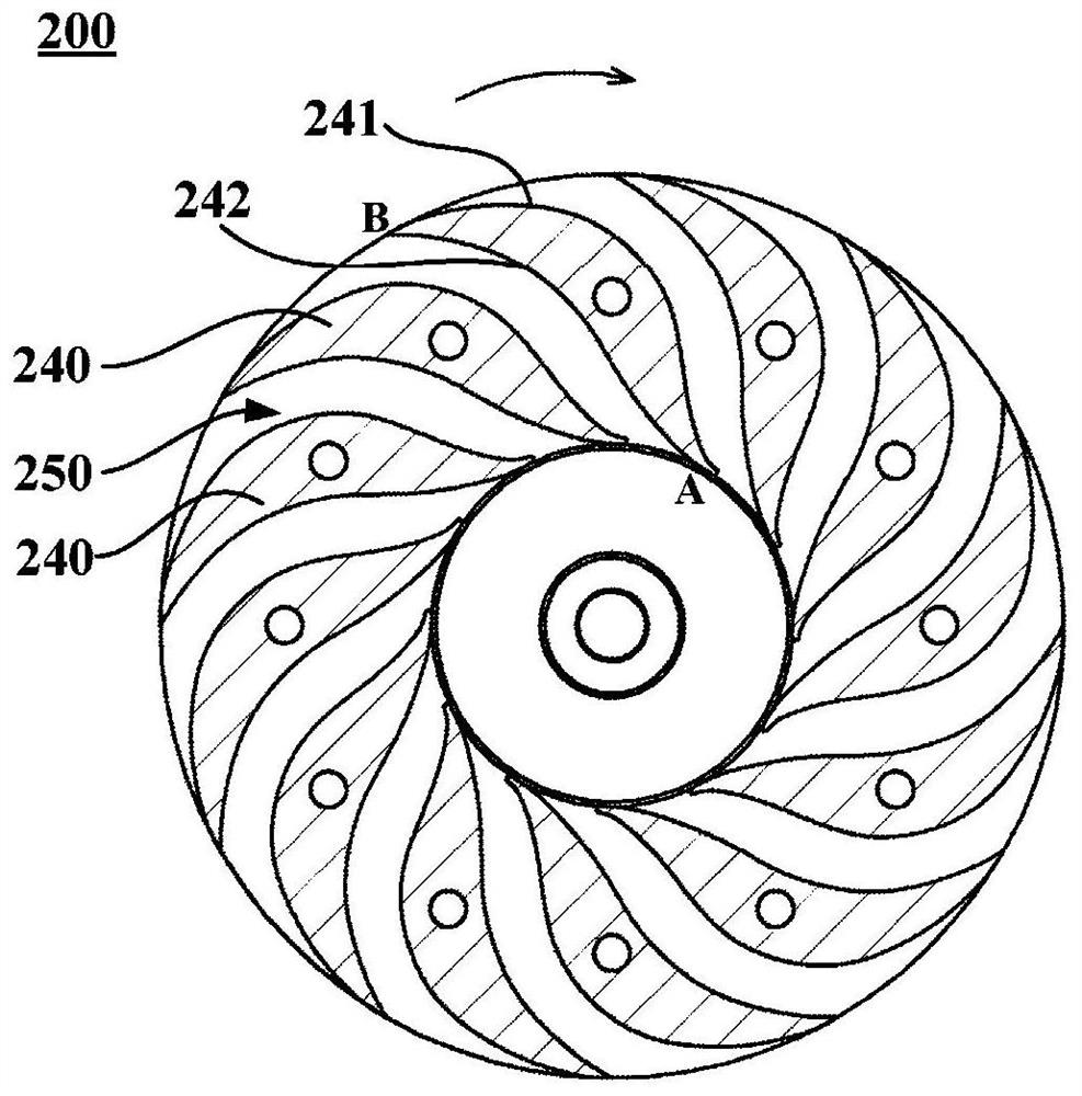
[0038] Refer below Figure 1 to Figure 12 The centrifugal compressor and the impeller 200 thereof according to the embodiment of the present invention will be described. In some figures, the x-axis is used to represent the axial direction of the impeller 200, which is also the axial direction of the motor 40 and its stator 41 and rotor 42; solid arrows are used to represent the airflow direction.

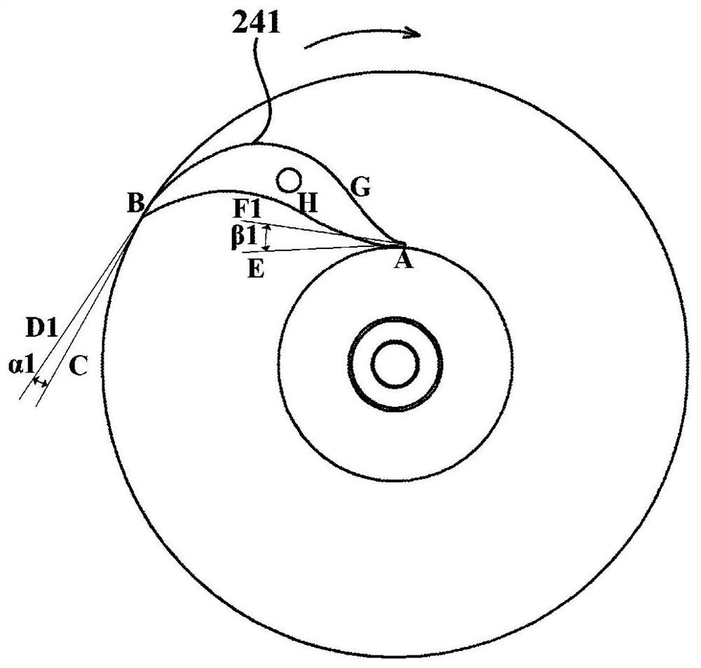
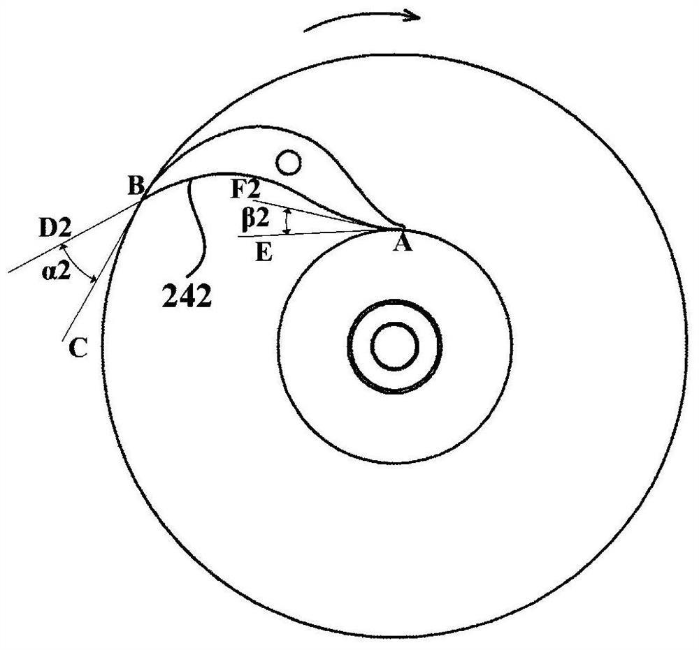
[0039] figure 1 is a schematic diagram of the profile of the impeller according to an embodiment of the present invention; figure 2 Yes figure 1 A schematic diagram of the installation angle of the pressure surface 241 of a blade 240 in the shown impeller 200; image 3 Yes figure 1 A schematic illustration of the mounting angle of the suction surface 242 of one of the blades 240 in the impeller shown.

[0040] The impeller 200 of the embodiment of the present invention is used in a centrifugal compressor, such as figure 1 As shown, the impeller 200 includes a plurality of bla...


PUM


Abstract

The invention provides a centrifugal compressor and an impeller thereof, the impeller comprises a plurality of blades arranged in the circumferential direction of the impeller, and a flow channel is formed between every two adjacent blades; each blade is of a backward bending type which is gradually bent in the direction deviating from the rotation direction of the impeller from the inlet end to the outlet end; and in the direction from the inlet end to the outlet end, the thickness of each blade is gradually increased and then gradually decreased. The impeller is higher in pneumatic efficiency, and miniaturization of the centrifugal compressor is facilitated.

Description

technical field [0001] The invention relates to the technical field of compressors, in particular to a centrifugal compressor and its impeller. Background technique [0002] Centrifugal compressors have the significant advantages of energy saving, high efficiency, stable operation and long service life. However, in the field of refrigeration, centrifugal compressors are suitable for large-flow, low-pressure work situations, and it is difficult to achieve high-efficiency, small-flow, high-pressure operation. Therefore, centrifugal compressors are used in large cooling capacity chillers. Small and medium-sized refrigeration systems use more screw compressors, scroll compressors (such as small central air conditioners, including multi-line compressors) and rolling rotor compressors. But these kinds of compressors operate far less efficiently than centrifugal compressors. Also, most of these types of compressors are lubricated with lubricating oil. It is very easy to cause p...

Claims


Application Information

Patent Timeline
Patent Type & Authority Applications(China)
IPC IPC(8): F04D29/28F04D29/30F04D17/12
CPCF04D29/286F04D29/30F04D17/12
Inventor 俞国新桂幸民殷纪强陈锦践李思茹朱万朋韩聪常云雪魏伟
Owner QINGDAO HAIER SMART TECH R & D CO LTD
Learn More