Self-moving type tunnel dust removal equipment

A dust removal equipment, self-moving technology, applied in mining equipment, dust prevention, human health protection and other directions, can solve the problems of wide distribution of dust, waste of water resources, fan heating, etc., to improve work safety, protect health, The effect of avoiding failure

Pending Publication Date: 2022-05-27
中铁工程装备集团隧道设备制造有限公司
View PDF1 Cites 0 Cited by
  • Summary
  • Abstract
  • Description
  • Claims
  • Application Information

AI Technical Summary

Problems solved by technology

[0004] However, these dust removal devices require manual on-site control, because the high dust concentration in the tunnel will affect the sight and health of the staff, so it is inconvenient to use. In addition, a large amount of dust will adhere to the dust collector with the change of operation time, which will affect the working ability of the fan, causing the fan Overheating will seriously cause the fan to overload and burn out;
[0005] In addition, the dust distribution range is wide, and the existing air duct cannot be adjusted or the adjustment range is limited, which affects the dust collection effect;
[0006] For wet tunnel dedusting vehicles, water consumption is required during dedusting work, and the existing equipment cannot effectively control the water volume according to the start and stop of the deduster, resulting in waste of water resources
[0007] To sum up, the use and research and development of domestic tunnel dust removal equipment is still in its infancy, and there are some problems. There is an urgent need for a dust removal equipment with independent mobility. The dust suction port can be adjusted in multiple directions to achieve efficient dust collection and solve the problem of Timely cleaning and maintenance and sewage problems, and equipped with intelligent control system to achieve energy saving, high efficiency and safety effects

Method used


Image

  • Self-moving type tunnel dust removal equipment
  • Self-moving type tunnel dust removal equipment
  • Self-moving type tunnel dust removal equipment

Examples


Embodiment 1

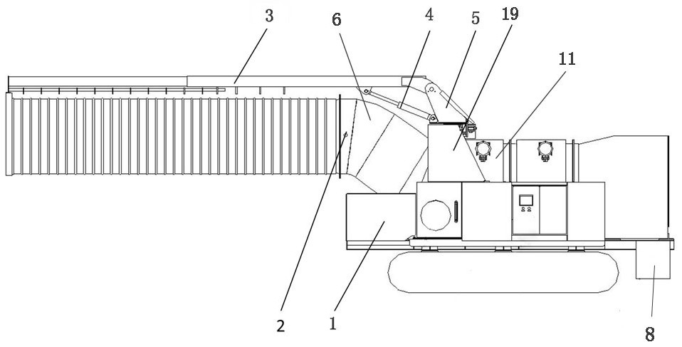
[0047] like Figures 1~7 As shown, a self-moving tunnel dust removal equipment includes a dust removal device, a traveling device, an air duct device and a sewage discharge device. The traveling device includes a carrier vehicle 1. The top of the carrier vehicle 1 is provided with an air duct device. One end is connected to the dust removal device, the dust removal device includes a fan 11, the sewage outlet of the dust removal device is connected to the sewage discharge device, and an intelligent control system is arranged between the dust removal device, the walking device, the air duct device and the sewage discharge device, and the air duct device includes The air duct 2 and the hanging device. The air duct 2 is fixed to the carrier vehicle 1 through the hanging device. The intelligent control system is used to control the hanging device to adjust the position of the air duct 2. The dust removal device is electrically connected to the intelligent control system. The device...

Embodiment 2

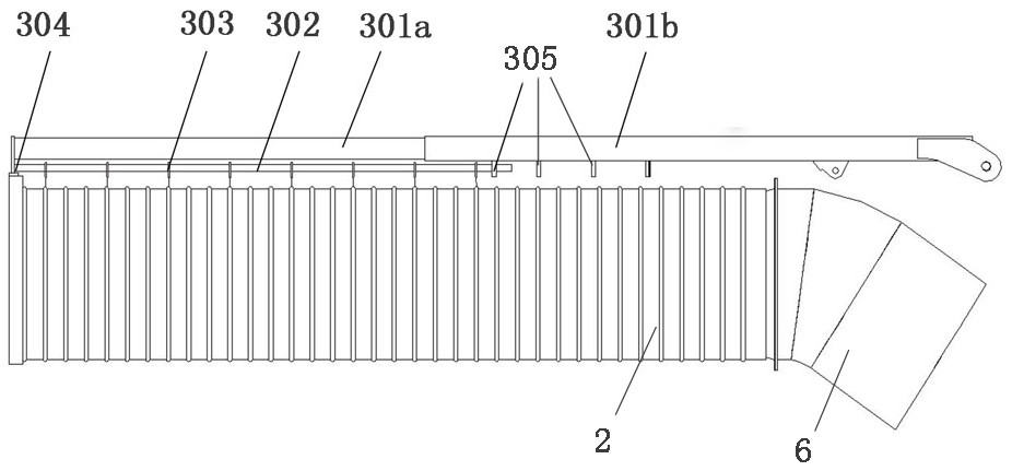
[0051] In combination with the above embodiment, the adjustment of the air duct 2 is optimized as follows Figure 2~4 shown:

[0052] The hanging device includes a telescopic mechanism 3, the telescopic mechanism 3 includes a telescopic rod 301, the telescopic rod 301 is a stepped column structure, and the telescopic rod 301 includes a large diameter end (marked as 301b in the figure) and a plurality of Small diameter end (marked as 301a in the figure), the large diameter end is sleeved outside the small diameter end, the small diameter end is slidably connected with the large diameter end, and the large diameter end and the small diameter end are circular, square or polygonal;

[0053] The lower side of the small diameter end of the telescopic rod 301 is provided with a hanging rod 302, the hanging rod 302 is a long round tube, and a plurality of hanging rings 303 are fixedly connected to the middle of the hanging rod 302 at an equal distance. A connecting ring 304 is arrang...

Embodiment 3

[0064] Based on Example 1, the dust removal mechanism is optimized as follows figure 1 , 6 and 7 as shown:

[0065] The dedusting device further includes a dedusting box, a spraying mechanism, a filtering mechanism and a dewatering mechanism are arranged inside the dedusting box, the nozzle ring is arranged at the position of the air inlet of the dedusting box, and the spraying mechanism includes a water tank and a nozzle, and the nozzle is arranged Inside the dust removal box body, the water tank is arranged outside the dust removal box body, a filter mechanism is arranged in the middle of the dust removal box body, and the filter mechanism includes a multi-layer filter screen;

[0066] The dehydration mechanism is arranged at the rear end of the dust removal box, and the dehydration mechanism includes an exhaust pipe, and the exhaust pipe and the dust box are an integrated structure;

[0067] The water tank and the spray head are connected through a water supply pipeline, ...


PUM


Abstract

The invention relates to self-moving type tunnel dust removal equipment which comprises a dust removal device, a walking device, an air duct device and a pollution discharge device, the walking device comprises a carrier loader, the top of the carrier loader is provided with the air duct device, one end of the air duct device is connected with the dust removal device, the dust removal device comprises a fan, and a pollution discharge opening of the dust removal device is connected with the pollution discharge device. An intelligent control system is arranged among the dust removal device, the walking device, the air duct device and the pollution discharge device, the intelligent control system comprises a main control module, a remote control unit, a detection unit and a communication unit, and the remote control unit is connected with the main control module through the communication unit; the main control module controls the dust removal device and the pollution discharge device to work through the detection unit in a PID control mode. The walking device is combined with the intelligent control system to realize remote control running or automatic running to bring the air duct device and the dust removal device to an area with high dust concentration for dust removal operation, and the intelligent control system is combined to realize automatic dust collection, dust removal and pollution discharge operation.

Description

technical field [0001] The invention belongs to the field of dust removal for tunnel construction, in particular to a self-moving tunnel dust removal device. Background technique [0002] With the development of infrastructure construction in my country, the amount of tunnel projects such as highways, railways and urban rail transit has increased year by year. In order to improve work efficiency and project quality, it has gradually become a trend to use automatic mechanical equipment for tunnel construction. Work can leave a lot of dust in the work area. These dusts not only seriously affect the health of construction workers, but also damage the surrounding environment of the tunnel project. More serious dust entering the machinery and equipment will cause damage to the machinery and equipment, and safety accidents are prone to occur in serious cases. [0003] In order to effectively reduce the dust concentration and collect and process the dust centrally, the prior art is...

Claims


Application Information

Patent Timeline
IPC IPC(8): E21F5/20E21F5/04E21F5/00E21F17/18E21F17/00
CPCE21F5/20E21F5/04E21F5/00E21F17/18E21F17/00Y02A50/2351
Inventor 姜继尚孙延飞童燕张思豪
Owner 中铁工程装备集团隧道设备制造有限公司
Why Eureka
Try Eureka