
Vaporization device for thin film deposition

A vaporization device and thin film deposition technology, applied in the direction of evaporation device, gaseous chemical plating, chemical instruments and methods, etc., can solve the problems of reducing vaporization efficiency, aggravating the design of vaporization device, and complicated production costs, so as to improve vaporization efficiency and prevent recondensation effect

Pending Publication Date: 2022-05-27
MI
View PDF7 Cites 0 Cited by
  • Summary
  • Abstract
  • Description
  • Claims
  • Application Information

AI Technical Summary

Problems solved by technology

However, the vaporization method of the decompression method can only vaporize a part of the liquid source, and there is always the problem of reducing the vaporization efficiency
Therefore, in order to vaporize all or more than the required amount of the liquid source, the structure of the vaporization device should become complicated or enlarged.
[0007] In addition, due to the complexity and size of the vaporization device, the source of vaporization in the vaporization device may be re-liquefied while flowing through the complicated flow path in the vaporization device.
In addition, when a large number of sources need to be vaporized, the vaporization device will be more complicated and larger. Therefore, while the above-mentioned problems are aggravated, the design of the vaporization device is more complicated and the production cost increases.

Method used


Image

  • Vaporization device for thin film deposition
  • Vaporization device for thin film deposition
  • Vaporization device for thin film deposition

Examples


Embodiment Construction

[0037] Embodiments of the technical idea of ​​the present invention will be described in detail with reference to the accompanying drawings. However, the present invention is not limited to the embodiments described here, and can be embodied in other forms. Rather, the embodiments described herein are provided so that this disclosure will be thorough and complete, and will fully convey the concept of the invention to those skilled in the art.

[0038] The present invention may be subject to various modifications and may have various forms, and aspects (or, examples) are described in detail herein. However, this is not intended to limit the present invention to a specific disclosed form, and it should be understood that all changes, equivalents, and substitutes included in the idea and technical scope of the present invention are included.

[0039] The terms used in this specification are used only to describe specific aspects (aspects; or, examples), and are not intended to l...


PUM


Abstract

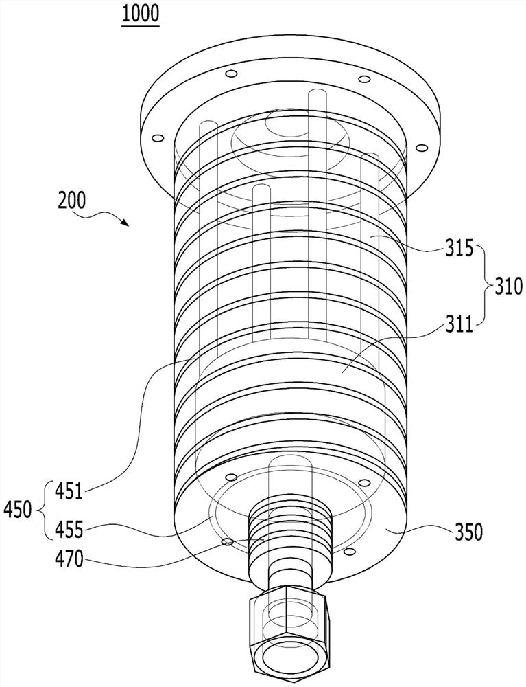
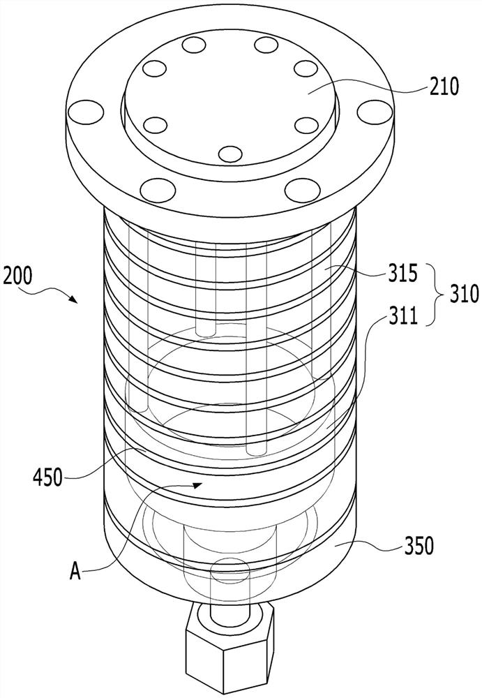
The vaporization device of the present invention may comprise: a sprayer that mixes a source injected through a source injection port and a carrier gas injected through a carrier gas injection port, and sprays the mixed gas; a vaporizing part having first and second vaporizing spaces for vaporizing the mixed gas ejected from the atomizer, and discharging the vaporized gas as a process gas through an outlet; and the heating part is used for keeping the mixed gas in the vaporization part at a preset temperature. The heating unit may include: a first heating unit arranged to surround the first vaporization space so as to maintain the temperature of the mixed gas in the first vaporization space; and a second heating part which is arranged together with the first heating part so as to surround the second vaporization space and maintain the temperature of the mixed gas in the second vaporization space.

Description

technical field [0001] The present invention relates to a vaporization device for thin film deposition, and more particularly to a vaporization device for thin film deposition with high vaporization efficiency used in semiconductor manufacturing. The heater structure can be improved to prevent the re-condensation of sprayed droplets. Background technique [0002] Generally, semiconductor elements or display elements, etc. are manufactured by performing a series of processes such as thin film deposition process and photolithography process using a semiconductor manufacturing apparatus. In such a series of processes, a thin film deposition process for forming a thin film on a substrate may be performed by a chemical vapor deposition (CVD) method or an atomic layer deposition (ALD) method. [0003] Generally, the thin film deposition process is a process of injecting a process gas into a process chamber to cause a reaction on a substrate (wafer) to form a thin film on the subst...

Claims


Application Information

Patent Timeline
Patent Type & Authority Applications(China)
IPC IPC(8): C23C16/448
CPCC23C16/4481H01L21/67017H01L21/67103B01D1/14B01D1/16B01D1/22C23C16/4486B01B1/005H01L21/67011
Inventor 金基南
Owner MI
Learn More