Slurry recycling device and method in building wall plastering construction

A technology for building walls and recycling devices, which is applied in construction, building structure, cleaning methods and appliances, etc. It can solve the problems of large contact area of ​​cement blocks, difficulty in peeling off cement blocks, and increased difficulty in crushing, so as to improve recycling efficiency Effect

Active Publication Date: 2022-05-27
PINGMEI SHENMA CONSTR ENG GROUP
View PDF8 Cites 0 Cited by
  • Summary
  • Abstract
  • Description
  • Claims
  • Application Information

AI Technical Summary

Problems solved by technology

[0004] During the plastering construction process, the plastering slurry dropped from the wall usually falls directly at the root of the construction wall, and the dropped plastering slurry often gathers at the root of the wall to condense or semi-condense, and finally condenses to form a block diameter Larger cement blocks; due to the large block diameter of the coagulated cement blocks, that is, the large contact area between the cement blocks and the wall and the ground, it is difficult to peel off the coagulated cement blocks from the ground and the wall. When recycling the cement block material that has fallen and solidified from the wall, due to the large diameter of the cement block, it is difficult to break after recycling, resulting in low recycling efficiency
[0005] Chinese patent document CN112252666B discloses a recovery device and recovery method for wall plastering materials used in building construction. In this patent document, a recovery device is set at the bottom of the wall, and the plastering material directly falls on the surface of the recovery device, and then the self-lubricating sticker The lubricating oil in the chip effectively helps the plastering material to drop and reduce the accumulation of the plastering material at the root of the wall. At the same time, the self-expanding moving ball and the fixed moving ball with different magnetic properties will move and vibrate after being impacted. Loosening is carried out so that the diameter of the stucco material block will not be too large during recycling, but this technical solution cannot collect the fallen stucco material. In addition, this technical solution contains a large amount of lubricating oil and spherical parts with different magnetic properties, and it needs to be washed repeatedly at high temperature Gas, etc. make the cost of the scheme higher and the construction more difficult

Method used


Image

  • Slurry recycling device and method in building wall plastering construction
  • Slurry recycling device and method in building wall plastering construction
  • Slurry recycling device and method in building wall plastering construction

Examples


Embodiment 1

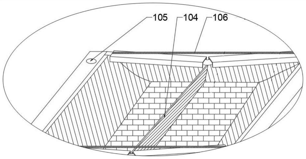
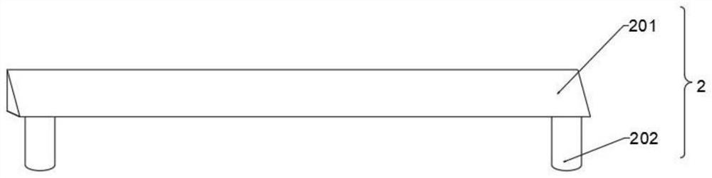
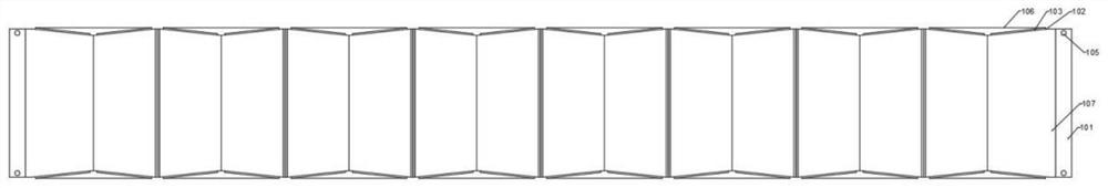
[0036] The technical solutions in the embodiments of the present invention will be clearly and completely described below with reference to the accompanying drawings in the embodiments of the present invention. Obviously, the described embodiments are only a part of the embodiments of the present invention, but not all of the embodiments. like figure 1 , 2 , 4, 5, 6, and 7, a slurry recovery device for building wall plastering works, including several collection boxes 1 and shaping rods 2, the collection box 1 includes two end plates 101, The plate 101 adopts an elongated plate-like structure, and a flexible side wall 102 and a flexible bottom plate 107 are arranged between the two end plates 101. The flexible side wall 102 and the flexible bottom plate 107 are respectively made of rubber material. The plate 101, the flexible side wall 102 and the flexible bottom plate 107 together constitute the collection cavity of the collection box 1, and a smooth film is arranged on the ...

Embodiment 2

[0040] This embodiment is an improvement scheme made on the basis of Embodiment 1, and its main structure is the same as that of Embodiment 1. The improvement points are as follows: image 3 As shown, the guide rod 201 is composed of an outer rod body 2011 , an inner core 2012 and a locking bolt 2013 . After locking, the two latches 202 are respectively arranged at the ends of the outer rod body 2011 and the inner core 2012. Especially in continuous operation, when the two ends of the collection boxes 1 to be installed are on the outer end plates 101 of the collection boxes 1, When the distance between the insertion holes (105) changes, by adjusting the position of the inner core 2012 on the outer rod body 2011, the distance between the two pins 202 can be fine-tuned to increase the application scene of the device.

Embodiment 3

[0042] This embodiment is an improvement scheme made on the basis of Embodiment 1, and its main structure is the same as that of Embodiment 1. The improvement points are as follows: image 3 As shown, support rods 108 are provided below the outer end plates 101 of the collection boxes 1 at the two ends, and two support rods 108 are provided under each of the outer end plates 101. The bottom end of the collection cavity is off the ground, so that the collection cavity can accommodate more slurry falling off the building wall. The bottom of the support rod 108 is installed with a pulley 109. The pulley 109 adopts a universal wheel structure, which is convenient for the use of Movement of slurry recovery unit for building wall plastering works.


PUM


Abstract

According to the slurry recycling device and method for the building wall plastering project, the slurry recycling device comprises a plurality of collecting boxes and a shaping rod, each collecting box comprises two end plates, a flexible side wall located between the two end plates and a flexible bottom plate, and the end plates, the flexible side walls and the flexible bottom plates jointly form a collecting cavity of the collecting boxes; every two adjacent collecting boxes are detachably connected together through an end plate, and inserting holes are formed in the end plates on the outer sides of the collecting boxes located at the two ends. The shaping rod comprises a flow guide rod and plug pins arranged at the two ends of the flow guide rod, and the plug pins at the two ends of the flow guide rod can be placed in the inserting holes of the collecting boxes at the two ends correspondingly. An elastic film for dividing the collecting cavity into two cavities is arranged between the two flexible side walls, two framework plates are arranged on the flexible side walls side by side, and an elastic pull rope is arranged between the two framework plates, so that slurry can be collected in time, and meanwhile, the situation that falling slurry is stacked into a large block diameter to be not beneficial to follow-up crushing utilization is prevented.

Description

technical field [0001] The invention relates to the field of construction, in particular to a recovery device and a recovery method for slurry in building wall plastering construction. Background technique [0002] With the improvement of people's living standards, the continuous expansion of the per capita living area and the improvement of the living environment, the development of industrial and civil buildings has been very rapid, and the accompanying building facades have also undergone tremendous changes, with various forms and building materials. There are more and more varieties of and decorative materials, and the wall plastering project is the last process of the entire building construction project. The plastering project is a traditional decorative project in which mortar is applied to the walls, floors, ceilings and surfaces of buildings. . [0003] Plastering engineering refers to the systematic construction process in which the plastering slurry is applied to...

Claims


Application Information

Patent Timeline
Patent Type & Authority Applications(China)
IPC IPC(8): B08B15/04E04F21/02
CPCB08B15/04E04F21/02Y02W30/91
Inventor 常欢欢胡洪雷张晓娟丁晓宇徐红星郑瑛瑛何朝永寇华伟李鑫磊姚月辉贝蕾杜淑燕魏俊收唐相伟张晶洁杨瑞张志彬李彦稳杨子轩胡永刚安晓旭吕照奇
Owner PINGMEI SHENMA CONSTR ENG GROUP
Why Eureka
Try Eureka