
Insect killing device for forest fruit insect pest prevention

A technology for pest control and extermination, which can be applied to devices for capturing or killing insects, cleaning methods using tools, cleaning methods using gas flow, etc. Improve cleaning efficiency, improve practicability, and facilitate the effect of shaking off

Active Publication Date: 2022-05-27
新泰市国有土门林场
View PDF3 Cites 2 Cited by
  • Summary
  • Abstract
  • Description
  • Claims
  • Application Information

AI Technical Summary

Problems solved by technology

[0002]In agricultural production, the disease and insect control of crops in fruit forest areas such as woodlands, fruit trees, and greenhouses has always been a relatively important task in agricultural production. The method of spraying pesticides is used to kill insects, but although spraying pesticides can kill insects, after several generations of reproduction, the pests will produce antibodies, which will gradually reduce the effect of pesticides, and some pesticides will remain on agricultural products. If you eat them for a long time It can cause chronic poisoning of humans and animals, and even death. Moreover, chemical control consumes petrochemical energy and has caused serious pollution to the rural environment. Its electric shock device kills the pests
[0003] However, the existing new-type insect extermination devices are often placed directly on the ground or hung on trees to directly attract pests. Such insect extermination devices generally can only attract flying insects, and cannot Extermination of reptiles has relatively large limitations in use, and the dead bodies of pests will be attached to the power grid on the extermination device, which requires manual cleaning on a regular basis, which is time-consuming and laborious, and has poor practicability

Method used


Image

  • Insect killing device for forest fruit insect pest prevention
  • Insect killing device for forest fruit insect pest prevention
  • Insect killing device for forest fruit insect pest prevention

Examples


Embodiment 1

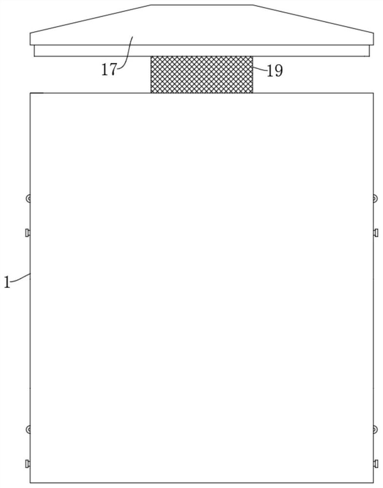
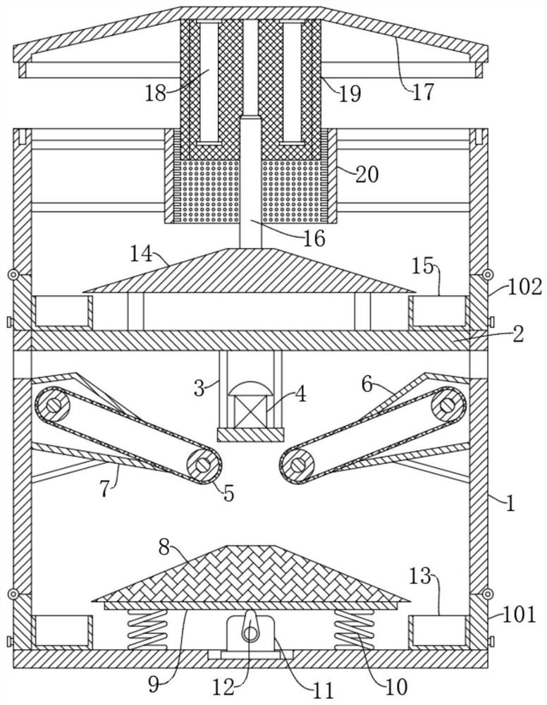
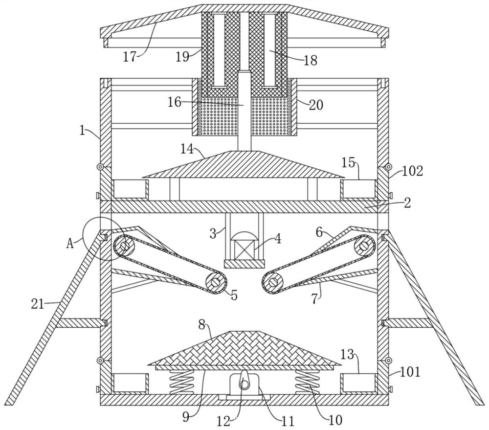
[0031] refer to Figure 1-Figure 6 , a pest control device for forest fruit pest control, comprising a pest control box 1, and also includes: a support plate 2, which is fixedly connected in the pest control box 1, wherein, the two sides of the pest control box 1 are close to the bottom of the support plate 2 There is an insect inlet; the odor inducer 4 is installed directly under the support plate 2 through the bracket 3; the conveyor 5 is symmetrically installed in the insect killing box 1, and is located below the insect inlet; the guide plate 6 is fixedly connected to the The insect box 1 is close to the inner side of the insect inlet, and the end away from the insect inlet is slidably connected to the conveyor belt on the conveyor 5; the scraper 7 is fixedly connected to the lower end of the insect control box 1 close to the conveyor 5, and is connected with the conveyor 5. The conveyor belt is slidably connected; the telescopic spring 10 is symmetrically and fixedly conn...

Embodiment 2

[0035] refer to Figure 1-Figure 6 , a kind of pest control device for forest fruit pest control, basically the same as embodiment 1, further is: the lower end of the support 3 is fixedly connected with a jet disc 24 through a connecting rod, and the lower end of the jet disc 24 is provided with jet ports on both sides , the bottom of the air cylinder 24 is fixedly connected with an air cylinder 28, a piston rod 25 is slidably connected in the air cylinder 28, the lower end of the piston rod 25 is connected with the conductive plate 8, and the air inlet and outlet of the air cylinder 28 are provided with the air injection port of the air injection disc 24. One-way valve, the air outlet of the air cylinder 28 is correspondingly connected with the air inlet of the air injection plate 24, and through the setting of the air injection plate 24, the air cylinder 28 and the piston rod 25, when the motor 11 drives the conductive plate 8 to vibrate up and down, the conductive plate 8 ca...

Embodiment 3

[0039] refer to Figure 1-Figure 6 , a pest control device for forest fruit pest control, which is basically the same as Embodiment 1, and further is: the upper end of the pest control box 1 is an opening, and a support rod 16 is installed on the top of the support plate 2, and the support rod 16 The top plate 17 is fixedly connected to the upper end of the top plate 17, the two sides of the top plate 17 close to the support rod 16 are fixedly connected with trap lights 18, and the outer side of the top plate 17 close to the trap lights 18 is fixedly connected to the grid 19. Then, when the flying pests fly towards the trapping light 18, the grid 19 outside the trapping light 18 will give electric shocks to the flying pests, so that the It kills and effectively improves the insecticidal effect of the device;

[0040] The support rod 16 is an electric lift rod, the top plate 17 is fixedly connected to the telescopic end of the electric lift rod, the insect control box 1 is fix...


PUM


Abstract

The invention discloses a pest killing device for forest fruit pest control, and belongs to the technical field of pest control. A deinsectization device for forest fruit insect pest prevention comprises a deinsectization box and further comprises a supporting plate fixedly connected into the deinsectization box, and insect inlets are formed in the positions, close to the lower portion of the supporting plate, of the two sides of the deinsectization box; the smell inducer is mounted under the supporting plate through a bracket; the conveyors are symmetrically arranged in the insect killing box and are positioned below the insect inlet; according to the device, pests can be lured and killed, and when the pests are killed, a current-conducting plate can be driven to vibrate, so that pest corpses attached to the current-conducting plate can be conveniently vibrated off and collected in a centralized mode, the pest corpses can be prevented from influencing the electric shock effect of the current-conducting plate, workers can conveniently clean the pest corpses, and the device is convenient to use. The practicability of the device is effectively improved, and the device is suitable for application and popularization.

Description

technical field [0001] The invention relates to the technical field of pest control, in particular to a pest control device for forest fruit pest control. Background technique [0002] In agricultural production, the pest control of crops in forest areas, fruit trees, greenhouses and other fruit forest areas has always been a relatively important task in agricultural production. In the prior art, pesticide spraying is generally used for pest control, but although pesticide spraying can kill pests , but after several generations of reproduction of pests, they will produce antibodies, which will lead to the gradual decline of the effect of pesticides, and some pesticides will remain on agricultural products. Prevention and control consumes petrochemical energy, and has caused serious pollution of the rural environment. In order to solve the above problems, a device that uses lights to attract insects and then uses the power grid to shock them when they are used has appeared on...

Claims


Application Information

Patent Timeline
IPC IPC(8): A01M1/02A01M1/04A01M1/22B08B5/02B08B1/02B08B7/02
CPCA01M1/02A01M1/04A01M1/223B08B5/02B08B7/02A01M2200/011A01M2200/012B08B1/12B08B1/20Y02A50/30
Inventor 徐杨陈涛周楠楠
Owner 新泰市国有土门林场
Learn More