Rolling bearing
A technology for rolling bearings and rolling surfaces, which is applied in the field of rolling bearings and can solve problems such as reducing manufacturing costs
- Summary
- Abstract
- Description
- Claims
- Application Information
AI Technical Summary
Problems solved by technology
Method used
Image
Examples
Embodiment approach 2
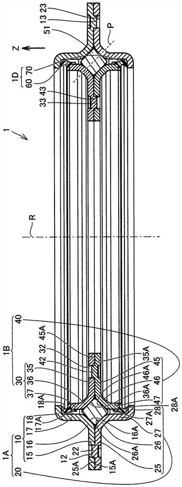
[0074] Next, Embodiment 2 of the rolling bearing 1 of the present disclosure will be described. The rolling bearing 1 in the second embodiment basically has the same structure as the rolling bearing 1 in the first embodiment, and has the same effect. However, Embodiment 2 is different from Embodiment 1 in that there is no labyrinth portion. Hereinafter, the points different from the case of Embodiment 1 will be mainly described.
[0075] refer to Figure 10 , the protruding portion 62 protrudes toward the inner peripheral surface 17A of the third portion 17 . The protruding portion 62 is directed toward the first space S with respect to the inner peripheral surface 17A. 1 The outer side extends in a sloping manner. The outer diameter and the inner diameter of the protruding portion 62 become larger as they approach the inner peripheral surface 17A. The front end portion 62A of the protruding portion 62 is in contact with the inner peripheral surface 17A. The protruding p...
Embodiment approach 3
[0080] Next, Embodiment 3 of the rolling bearing 1 of the present disclosure will be described. The rolling bearing 1 in the third embodiment basically has the same structure as the rolling bearing 1 in the first embodiment, and has the same effect. However, Embodiment 3 is different from Embodiment 1 in that each of the first inner ring 30 and the second inner ring 40 has a curved portion. Hereinafter, different points from the case of Embodiment 1 will be described.
[0081] refer to Figure 12 , the first inner ring 30 includes a first curved portion 38 . The first bent portion 38 is arranged so as to be connected to an end portion of the ninth portion 37 on the side opposite to the eighth portion 36 in the Z-axis direction, and is bent radially outward of the ninth portion 37 . The first bent portion 38 is arranged to face the third portion 17 in the Z-axis direction. The first curved portion 38 has an annular shape. A part of the end surface 38A of the first curved p...
Embodiment approach 4
[0089] Next, Embodiment 4 of the rolling bearing 1 of the present disclosure will be described. The rolling bearing 1 in the fourth embodiment basically has the same structure as the rolling bearing 1 in the third embodiment, and has the same effect. However, Embodiment 4 is different from Embodiment 3 in that there is no labyrinth portion. Hereinafter, the point which is different from the case of Embodiment 1 will be mainly described.
[0090] refer to Figure 14 , the protruding portion 62 of the first sealing member 60 protrudes toward the outer peripheral surface 37A of the ninth portion. The protruding portion 62 protrudes radially inward. The protruding portion 62 is directed toward the first space S with respect to the outer peripheral surface 37A. 1 The outer side extends in a sloping manner. The front end portion 62A of the protruding portion 62 is in contact with the outer peripheral surface 37A. The protruding portion 72 of the second sealing member 70 protru...
PUM
 Abstract
Description
Claims
Application Information
 - Generate Ideas
- Intellectual Property
- Life Sciences
- Materials
- Tech Scout
- Unparalleled Data Quality
- Higher Quality Content
- 60% Fewer Hallucinations
Browse by: Latest US Patents, China's latest patents, Technical Efficacy Thesaurus, Application Domain, Technology Topic, Popular Technical Reports.
© 2025 PatSnap. All rights reserved.Legal|Privacy policy|Modern Slavery Act Transparency Statement|Sitemap|About US| Contact US: help@patsnap.com


