
Impeller with high-low curved surface structure

A curved surface structure and impeller technology, which is applied to non-variable pumps, pump components, and parts of pumping devices for elastic fluids, etc., can solve the problem of uncontrollability, affecting the service life of the product, and affecting the center shaft hole and the impeller body verticality etc.

Pending Publication Date: 2022-05-24
浙江得业电机科技有限公司
View PDF0 Cites 0 Cited by
  • Summary
  • Abstract
  • Description
  • Claims
  • Application Information

AI Technical Summary

Problems solved by technology

Since the impeller body is in direct contact with the outer circle of the shaft, the impeller body is in contact with the outer circle at the same height as the shaft, and there are ribs here to strengthen the shaft, so the materials are concentrated here. When the impeller is in the plastic mold During internal molding, it is difficult for the junction between the impeller body and the outer circle of the shaft to dissipate heat quickly and evenly, and it is easy to produce irregular deformation and uncontrollable, which in turn affects the verticality between the central shaft hole and the impeller body, so that when the impeller works The radial runout will be relatively large. Generally, about 70% of the products will exceed the radial runout by more than 1.2mm (the qualified value of the radial runout is less than 0.8mm). The working noise will also increase and affect the product. service life

Method used


Image

  • Impeller with high-low curved surface structure
  • Impeller with high-low curved surface structure
  • Impeller with high-low curved surface structure

Examples


Embodiment Construction

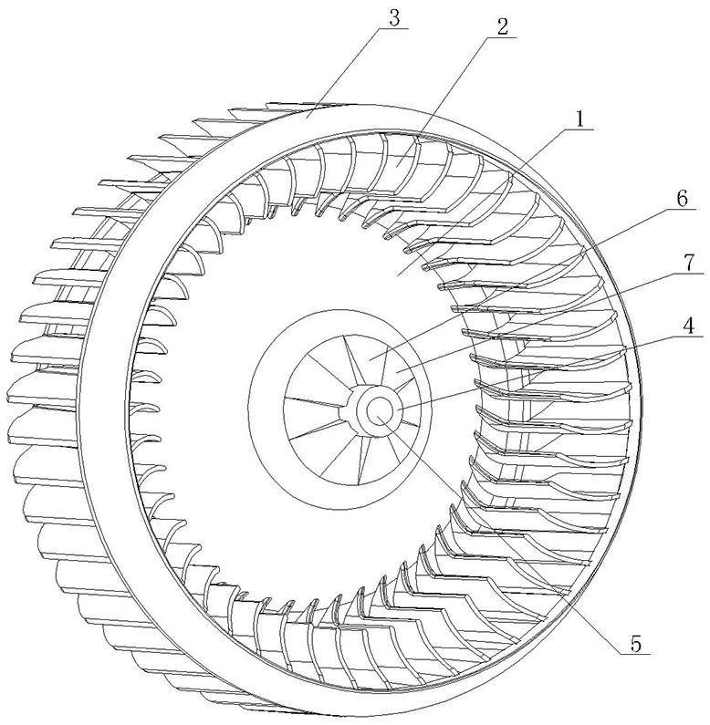
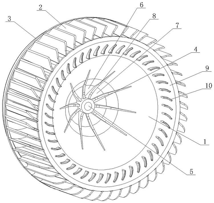
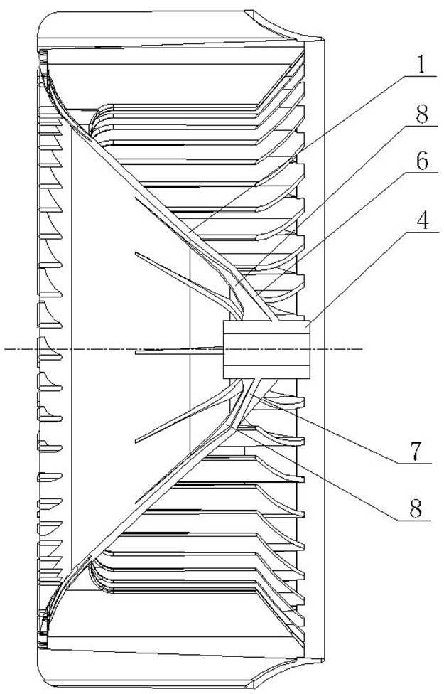
[0015] As shown in the figure, the impeller with high and low curved surface structure of the present invention includes an impeller body 1, a blade 2 and a blade outer ring 3. The impeller body 1 is a conical thin shell, the lower end of the blade 2 is connected to the outer edge of the impeller body 1, and the blade 2 The upper end of the blade is connected to the inner ring of the blade outer ring 3, the outer edge of the impeller body 1 is provided with a rounded transition curved surface 9, and the rounded transition curved surface 9 is provided with a small blade 10 on the circumference, and the small blade 10 corresponds to the blade 2 one by one. Arranged at the same circumferential angle, the center of the impeller body 1 is provided with a shaft 4, the shaft 4 has a central shaft hole 5, and the central shaft hole 5 is used for connection with the motor shaft. The impeller body 1, the blade 2, the blade outer ring 3, The small blade 10 and the shaft 4 are integrally i...


PUM


Abstract

The impeller of the high-low curved surface structure comprises an impeller body, blades and a blade outer ring, the impeller body is conical, a shaft rod is arranged in the center of the impeller body and provided with a central shaft hole, and the impeller body, the blades, the blade outer ring and the shaft rod are integrally formed in an injection molding mode. The impeller is characterized in that the position, close to the shaft rod, of the impeller body is connected with the outer circle surface of the shaft rod through high and low curved surfaces which are circumferentially distributed, the high curved surfaces and the low curved surfaces are arranged in a staggered mode, even number of rib plates are evenly distributed on the outer circle surface of the shaft rod, and the rib plates correspond to the boundaries of the high and low curved surfaces to separate the high and low curved surfaces. The high curved surface is connected with the top of the rib plate, and the low curved surface is connected with the waist of the rib plate. The connecting part of the impeller body and the shaft rod can be quickly and uniformly cooled during molding in a plastic mold, so that the better perpendicularity between the central shaft hole and the impeller body is ensured, the radial runout of an impeller product during working is small, the working noise is reduced, and the service life is prolonged.

Description

technical field [0001] The invention relates to an automobile air conditioner fan, in particular to an impeller of the automobile air conditioner fan. Background technique [0002] The impeller of the automobile air-conditioning fan needs to rotate at high speed during operation. The impeller of the automobile air-conditioning fan in the prior art includes an impeller body, blades and an outer ring of the blades. The impeller body is conical, and the lower end of the blade is connected to the outer edge of the impeller body. The upper end of the blade is connected to the inner ring of the outer ring of the blade, the center of the impeller body is provided with a shaft, the shaft has a central shaft hole, and the central shaft hole is used for the installation of the motor shaft. The impeller body, the blade, the outer ring of the blade and the shaft are One-piece injection molding. Since the impeller body is directly connected to the outer circle of the shaft, the impeller...

Claims


Application Information

Patent Timeline
IPC IPC(8): F04D29/28F04D29/30F04D29/58F04D29/66
CPCF04D29/283F04D29/30F04D29/5806F04D29/584F04D29/666F04D29/667
Inventor 孙晓钦张炳杰何羡乐王永广
Owner 浙江得业电机科技有限公司
Learn More