Controllable valve pesticide spraying agricultural fertilizer applicator
A technology of fertilizer applicator and agriculture, which is applied in agriculture, fertilizer applicator, agricultural gas emission reduction and other directions, can solve the problems of uncontrollable spraying amount, waste of chemicals, inability to adjust the amount of spraying of chemicals according to needs, etc., so as to easily and quickly control the unlocking mechanism. The effect of exercise and waste reduction
- Summary
- Abstract
- Description
- Claims
- Application Information
AI Technical Summary
Problems solved by technology
Method used
Image
Examples
Embodiment 1
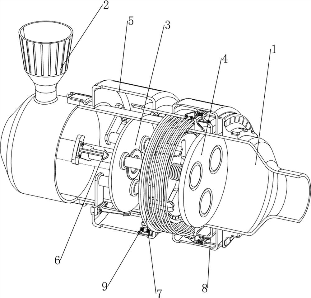
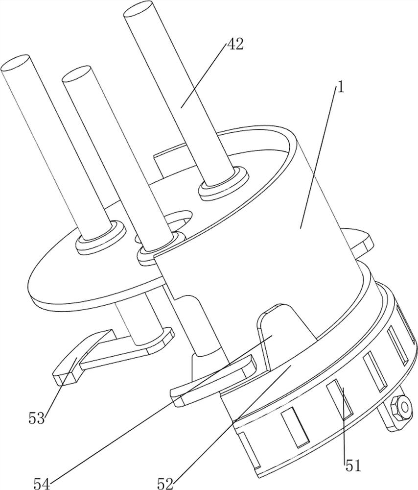
[0070] A controllable valve spraying chemical agricultural fertilizer applicator, such as figure 1 and figure 2 As shown in the figure, it includes a connecting pipe 1, a water inlet pipe 2, a first water baffle 3, a water boiling mechanism 4 and a sliding driving mechanism 5. The upper left side of the connecting pipe 1 is provided with a water inlet pipe 2, and the middle part of the connecting pipe 1 is provided with a first water inlet pipe 2. In the water baffle 3, a water boiling mechanism 4 is arranged in the middle of the connecting pipe 1, and a sliding driving mechanism 5 is arranged on the left part of the connecting pipe 1, and the sliding driving mechanism 5 cooperates with the water boiling mechanism 4.
[0071] When people need to spray and fertilize chemicals, they can first introduce the chemicals into the connecting pipe 1 through the water inlet pipe 2, and then they can rotate the sliding driving mechanism 5, and the sliding driving mechanism 5 can drive t...
Embodiment 2
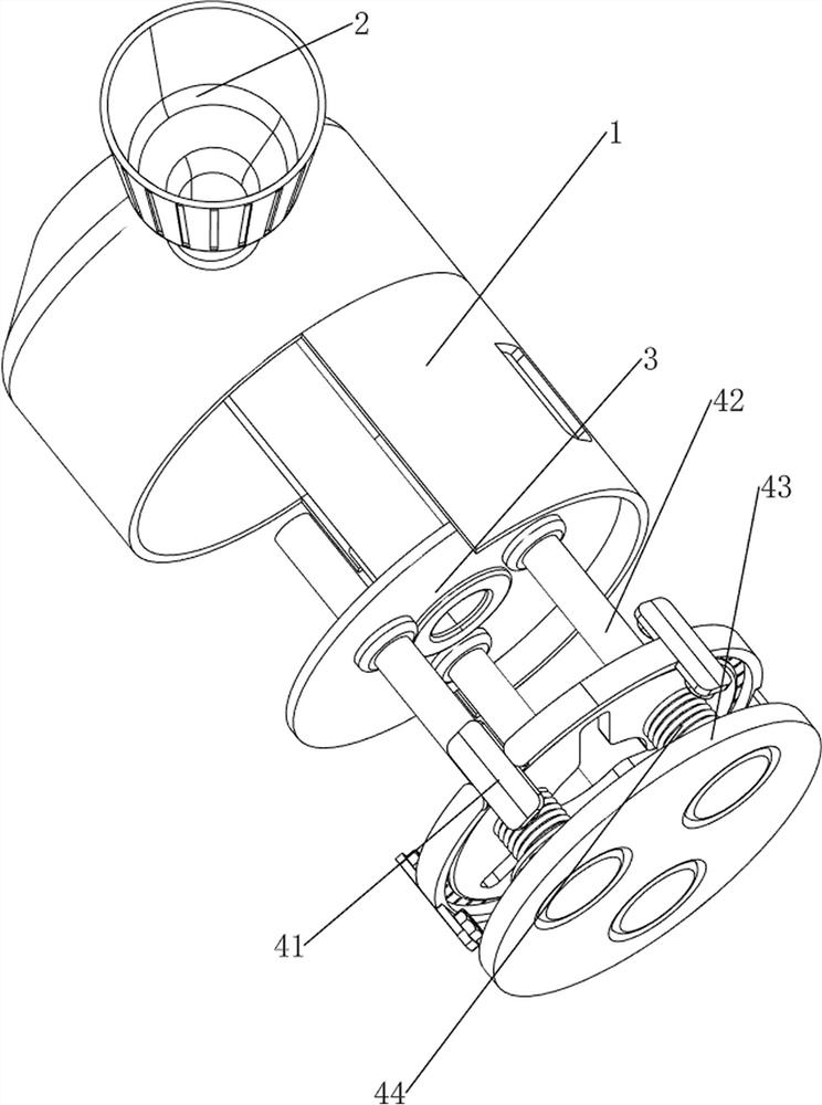
[0073] In a preferred embodiment of the present invention, as Figure 4-Figure 6 As shown, the water boiling mechanism 4 includes a first sliding sleeve 41 , a sliding water blocking rod 42 , a second water blocking plate 43 and a first spring 44 . The upper evenly sliding type is provided with sliding water blocking rods 42, the number of sliding water blocking rods 42 is three, the sliding water blocking rods 42 are slidably connected with the first water blocking plate 3, and the middle part of the connecting pipe 1 is provided with a second water blocking plate 43. The second water blocking plate 43 is located on the right side of the first sliding sleeve 41. The second water blocking plate 43 is slidably matched with the sliding water blocking rod 42. Both ends of a spring 44 are respectively connected to the second water blocking plate 43 and the sliding water blocking rod 42 .
[0074] After people add the medicament, they rotate the sliding driving mechanism 5, and th...
Embodiment 3
[0078] In a preferred embodiment of the present invention, as Figure 7-Figure 15 As shown, a locking mechanism 6 is also included. The locking mechanism 6 includes a third driving rod 61, a second sliding sleeve 62, a first sliding locking rod 63 and a second spring 64. The right sides of the three first driving rods 53 are A third driving rod 61 is provided, and a second sliding sleeve 62 is evenly arranged in the middle of the connecting pipe 1 . The rod 63, the first sliding locking rod 63 cooperates with the third driving rod 61, the three first sliding locking rods 63 are all sleeved with a second spring 64, and the two ends of the second spring 64 are respectively connected to the second sliding sleeve 62. and the first sliding locking lever 63 .
[0079] In the process of controlling the spraying of the medicine, the movement of the first driving rod 53 to the right can drive the third driving rod 61 to move to the right. When the third driving rod 61 moves to the rig...
PUM
 Abstract
Description
Claims
Application Information
 - R&D
- Intellectual Property
- Life Sciences
- Materials
- Tech Scout
- Unparalleled Data Quality
- Higher Quality Content
- 60% Fewer Hallucinations
Browse by: Latest US Patents, China's latest patents, Technical Efficacy Thesaurus, Application Domain, Technology Topic, Popular Technical Reports.
© 2025 PatSnap. All rights reserved.Legal|Privacy policy|Modern Slavery Act Transparency Statement|Sitemap|About US| Contact US: help@patsnap.com


