
Lathe spindle center hole opening device

A lathe spindle and center hole technology, applied in auxiliary devices, boring/drilling, drilling/drilling equipment, etc., can solve the problems of time-consuming and labor-intensive drilling of center holes, increased power consumption, and high labor intensity. The effect of reducing processing errors, improving production efficiency, and reducing labor intensity

Pending Publication Date: 2022-05-20
娄底市中厚机械制造有限公司
View PDF0 Cites 0 Cited by
  • Summary
  • Abstract
  • Description
  • Claims
  • Application Information

AI Technical Summary

Problems solved by technology

[0002] When machining shaft parts, it is often necessary to drill a center hole on the end face of the part. At present, there is no standard equipment for directly drilling the center hole except special machines such as double-sided milling and machining centers. The working steps of the circle and the end face of the car are separated, especially the center hole is generally selected for the positioning and processing reference of the shaft and cake parts. At present, most of them are processed on the lathe. In addition to the double-sided milling, the shaft parts must be supported by the center frame to punch the center hole. , not only requires repeated clamping and labor-intensive drilling, but it is more time-consuming and labor-intensive to punch the center hole of large-scale shaft cake parts. Increase power consumption and require a separate frame (or machine body) to occupy a certain amount of workshop space. At present, all solutions require repeated clamping or moving the tailstock or center frame. The processing efficiency is low and the labor intensity is high, which cannot meet the requirements. Production needs, therefore, there is an urgent need for a lathe spindle center hole opening device

Method used

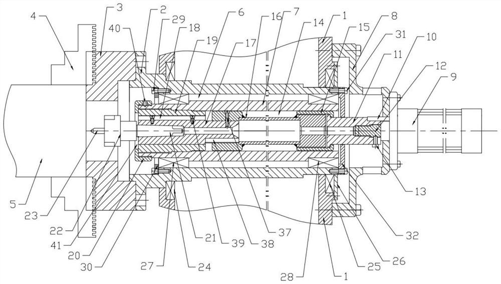
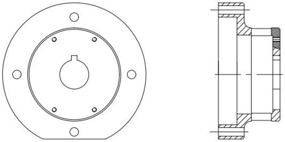
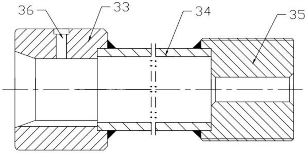

Image

  • Lathe spindle center hole opening device
  • Lathe spindle center hole opening device
  • Lathe spindle center hole opening device

Examples


Embodiment Construction

[0016] In describing the present invention, it is to be understood that the terms "upper", "lower", "front", "rear", "left", "right", "inner", "outer", "centre" etc. indicate The orientation or positional relationship is based on the orientation or positional relationship shown in the drawings, which is only for the convenience of describing the present invention and simplifying the description, and does not indicate or imply that the referred device or element must have a specific orientation configuration and operation, so it cannot be construed as a limitation of the invention.

[0017] In the description of the present invention, it should also be noted that, unless otherwise clearly specified and limited, the terms "equipped with", "installed", "connected", "connected" and so on should be understood in a broad sense, for example, it can be fixed The connection can also be a detachable connection, or an integrated connection, it can be a mechanical connection, it can also ...


PUM


Abstract

The invention discloses a lathe spindle center hole punching device which comprises a spindle box, a lathe spindle is rotationally connected into the spindle box, a chuck is connected to one end of the lathe spindle, a plurality of clamping jaws are evenly connected to the chuck, workpieces are installed in the clamping jaws, an installation cavity is formed in the lathe spindle, and a center hole is formed in the installation cavity. An inner shaft is rotationally connected into the mounting cavity, a hollow cavity is formed in the inner shaft, the end, away from the air cylinder base, of the coupler extends into the hollow cavity and is connected with a connecting nut, a connecting rod is connected into the connecting nut, the other end of the connecting rod is connected with a Morse sleeve, and a Morse cone is connected into the Morse sleeve. The end, close to the chuck, of the Morse cone is connected with a drill chuck, and the drill chuck is connected with a center drill. Compared with the prior art, the device has the advantages of being novel in structure, reasonable in design, low in working labor intensity and high in production efficiency.

Description

technical field [0001] The invention relates to the technical field of machining, in particular to a device for opening a central hole of a lathe spindle. Background technique [0002] When machining shaft parts, it is often necessary to drill a center hole on the end face of the part. At present, there is no standard equipment for directly drilling the center hole except special machines such as double-sided milling and machining centers. The working steps of the circle and the end face of the car are separated, especially the center hole is generally selected for the positioning and processing reference of the shaft and cake parts. At present, most of them are processed on the lathe. In addition to the double-sided milling, the shaft parts must be supported by the center frame to punch the center hole. , not only requires repeated clamping and labor-intensive drilling, but it is more time-consuming and labor-intensive to punch the center hole of large-scale shaft cake part...

Claims


Application Information

Patent Timeline
Patent Type & Authority Applications(China)
IPC IPC(8): B23B41/02B23B47/00B23B25/00B23Q11/00
CPCB23B41/02B23B47/00B23B25/00B23Q11/00Y02P70/10
Inventor 周铭梁鸿梁泽芸
Owner 娄底市中厚机械制造有限公司
Learn More