
Cooling waterway system and offshore wind power converter

A cooling waterway and water cooling system technology, applied in cooling/ventilation/heating transformation, wind power generation, conversion of AC power input to DC power output, etc., can solve problems such as frequent manual air supply of expansion tanks

Pending Publication Date: 2022-05-17
SHENZHEN HOPEWIND ELECTRIC CO LTD
View PDF0 Cites 0 Cited by
  • Summary
  • Abstract
  • Description
  • Claims
  • Application Information

AI Technical Summary

Problems solved by technology

[0008] The technical problem to be solved by the present invention is to propose a cooling waterway system, which can realize automatic air supply and exhaust to adjust the system pressure, has high reliability and long service life, and overcomes the problem that the expansion tank needs frequent manual air supply. Solve the problem that the voltage stabilizing device needs to be installed at the highest point of the system, making the structural layout of the entire water cooling system more compact and flexible

Method used


Image

  • Cooling waterway system and offshore wind power converter
  • Cooling waterway system and offshore wind power converter
  • Cooling waterway system and offshore wind power converter

Examples


Embodiment 1

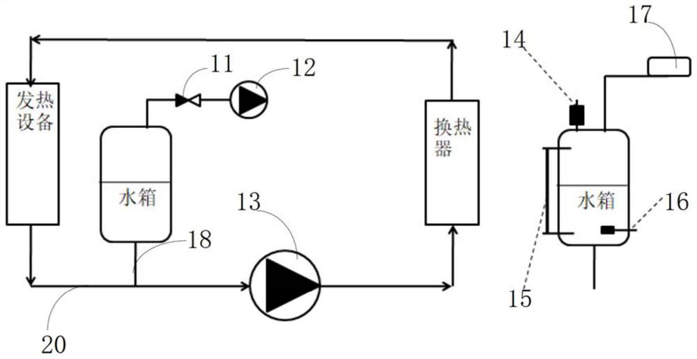
[0027] see image 3 , image 3 It is a connection diagram of the cooling water system in Embodiment 1 of the present invention; this embodiment discloses a cooling water system, including a gas pressure stabilizing device for flexibly controlling the working pressure of the cooling liquid in the water system, heating equipment and heat exchange The gas pressure stabilizing device includes a water tank, a water pump 13 connected to the water tank, and an air supply pump 12 for supplying air to the water cooling system when the pressure of the water cooling system is lower than the preset pressure. The water tank is provided with an inlet The air inlet, the air supply pump 12 is arranged on the air inlet, the generator and the heat exchanger are connected through the first pipeline 20, and the first pipeline 20 is also equipped with a water pump for driving the first pipeline for water-cooling flow 13. The water tank is connected to the first pipeline 20 through the second pipe...

Embodiment 2

[0036] In this embodiment, on the basis of Embodiment 1, the water inlet of the heating device is provided with a circulation pipeline connected to the water tank and used to circulate the water in the water tank and the first pipeline of the cooling water system. The road connects the water tank with the heating equipment in parallel.

Embodiment 3

[0038] This embodiment is based on the first embodiment, and the difference is that: the water tank of the gas pressure stabilizing device is connected to the water outlet of the water pump through the second pipeline.


PUM


Abstract

The invention discloses a cooling water path system which comprises a gas pressure stabilizing device, a heating device and a heat exchanger, the gas pressure stabilizing device comprises a water tank, a water pump connected with the water tank and a gas supplementing pump, the water tank is provided with a gas inlet, the gas supplementing pump is arranged on the gas inlet, and the heat exchanger is arranged on the gas inlet. The heating device and the heat exchanger are connected through a first pipeline, the first pipeline is further provided with a water pump used for driving the first pipeline to conduct water cooling flowing, and the water tank is connected to the first pipeline through a second pipeline. The cooling water path system can achieve automatic air supply and exhaust to adjust the system pressure, is high in reliability and long in service life, solves the problem that an expansion tank needs frequent manual air supply, solves the problem that a pressure stabilizing device needs to be installed at the highest point of the system, and enables the whole water cooling system to be more compact and flexible in structural arrangement.

Description

technical field [0001] The invention relates to the technical field of high-power power electronic equipment, in particular to a cooling waterway system and an offshore wind power converter. Background technique [0002] In the field of high-power power electronic equipment, such as wind power and variable frequency drive, with the increase of equipment power density, heat dissipation has become a very difficult problem. For high-power power electronic equipment, the simple air cooling technology can no longer meet the cooling requirements, and liquid cooling is a more effective method than air cooling. Liquid cooling continuously provides cooling medium with stable pressure and flow rate to the system through the circulating cooling system. Commonly used cooling systems are divided into open systems and closed systems. Open cooling systems have problems such as scaling, corrosion, and large water consumption. Therefore, closed circulation cooling systems have become the de...

Claims


Application Information

Patent Timeline
Patent Type & Authority Applications(China)
IPC IPC(8): H05K7/20H02M7/00H02M1/00
CPCH05K7/20263H05K7/20272H02M1/00H02M7/003Y02E10/76
Inventor 周泽平夏宽陈培强周党生王琰
Owner SHENZHEN HOPEWIND ELECTRIC CO LTD
Learn More