Optimized structure of power distribution network

A technology of power distribution network and structure optimization, applied in the direction of fixed capacitor components, printed circuits connected with non-printed electrical components, printed circuits, etc. Polarity relationship and other issues to achieve the effect of reducing impedance and improving the power distribution network

Pending Publication Date: 2022-05-17
GIGA FORCE ELECTRONICS CO LTD
View PDF0 Cites 0 Cited by
  • Summary
  • Abstract
  • Description
  • Claims
  • Application Information

AI Technical Summary

Problems solved by technology

[0003] The current power distribution network will adopt the scheme of adding as many capacitors as possible, without considering the distance and polarity relationship between capacitors. Although the power distribution network can be optimized by increasing the number of capacitors, it will be limited by the space of the circuit board. The cost will also increase further, and simply increasing the capacitance at high frequency will not solve the problem

Method used


Image

  • Optimized structure of power distribution network
  • Optimized structure of power distribution network
  • Optimized structure of power distribution network

Examples


Embodiment 1

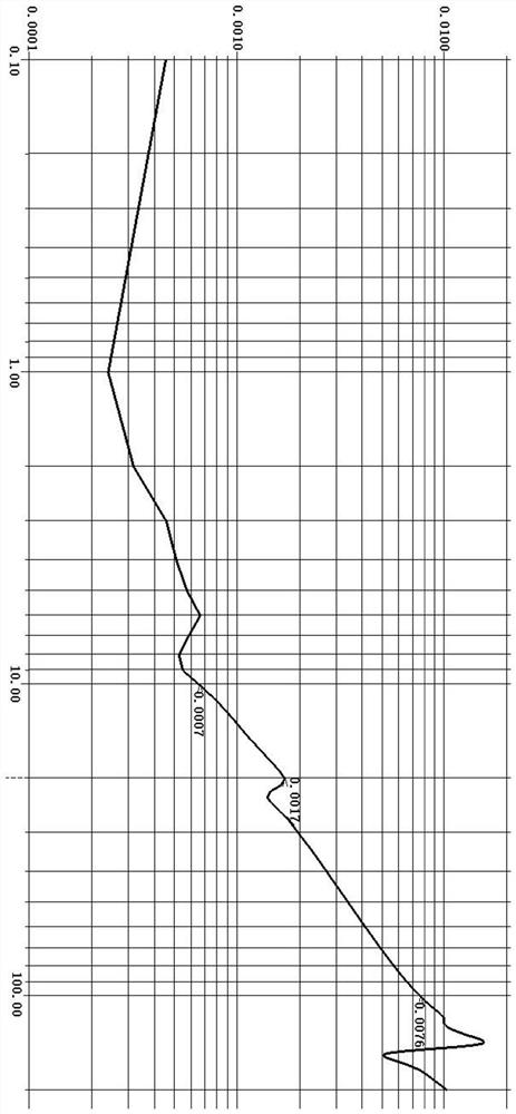
[0051] image 3 It is a schematic diagram of the impedance curve of the power distribution network detected at different frequencies by using the unoptimized structure of the existing power distribution network, Figure 4 Schematic diagram of the impedance curve of the power distribution network detected at different frequencies after using the optimized structure for the existing power distribution network, by comparison image 3 and Figure 4 To test the optimization effect of the optimized structure, the abscissa in the figure is the frequency, and the ordinate is the impedance of the power distribution network. It can be found that when the frequency is 10MHz, Figure 4 The impedance of the power distribution network dropped from 0.7mohm to 0.6mohm, when the frequency is 20MHz, Figure 4 The impedance of the power distribution network dropped from 1.7mohm to 1.3mohm, when the frequency is 100MHz, Figure 4 The impedance of the power distribution network dropped from 7.6mo...

Embodiment 2

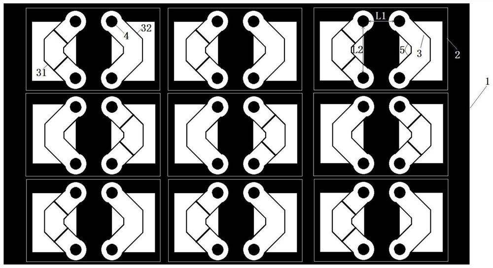
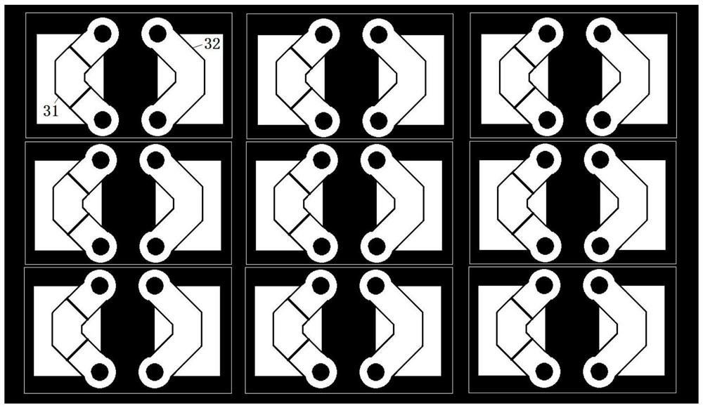
[0053] Figure 4 It is a schematic diagram of the impedance curve of the power distribution network detected at different frequencies after using the optimized structure for the existing power distribution network, Figure 5 A schematic diagram of the impedance curves of the power distribution network detected at different frequencies after only allowing the different electrodes 3 of each capacitor 2 to approach each other in the optimized structure for the existing power distribution network, by comparison Figure 4 and Figure 5 To test the optimization effect of the optimized structure, the abscissa in the figure is the frequency, and the ordinate is the impedance of the power distribution network. It can be found that when the frequency is 10MHz, Figure 4 There is no change in the impedance of the power distribution network in the frequency of 20MHz, Figure 4 The impedance of the power distribution network dropped from 1.4mohm to 1.3mohm, when the frequency is 100MHz, ...


PUM


Abstract

The invention provides an optimized structure of a power distribution network, comprising a circuit board in which a power network and a ground network are configured; the plurality of capacitors are arranged on the circuit board, each capacitor comprises two electrodes, and the two electrodes are respectively connected with a power supply network and a ground network through a double-via-hole structure; the double-via-hole structure comprises two via holes arranged at two ends of the electrodes respectively, fan holes are formed between the via holes, and the fan holes corresponding to the two electrodes of each capacitor are arranged oppositely. The optimized structure of the power distribution network has the beneficial effects that the fan holes of the capacitors are oppositely arranged, so that the electrodes with different polarities of the capacitors are close to each other, and meanwhile, the first via hole distance between two corresponding electrodes and the second via hole distance between two via holes are reduced to obtain the optimized structure; the impedance of the power distribution network can be effectively reduced, the limited circuit board space is utilized for optimization, the manufacturing cost does not need to be increased, and a better power distribution network is obtained through the optimized structure.

Description

technical field [0001] The invention relates to the technical field of power distribution networks, in particular to an optimized structure of a power distribution network. Background technique [0002] In the field of semiconductor chip testing, the integration of chips is getting higher and higher, the types of power sources are also increasing, and the speed has been increasing. Among them, the impedance of the power distribution network on the circuit board used by the chip has always been a concern. Important parameters. [0003] The current power distribution network will adopt the scheme of adding as many capacitors as possible, without considering the distance and polarity relationship between capacitors. Although the power distribution network can be optimized by increasing the number of capacitors, it will be limited by the space of the circuit board. The cost will also increase further, and simply increasing the capacitance at high frequency will not solve the pr...

Claims


Application Information

Patent Timeline
IPC IPC(8): H01G4/228H01G4/38H05K1/18
CPCH01G4/228H01G4/38H05K1/182
Inventor 周文中倪卫华郑朝晖
Owner GIGA FORCE ELECTRONICS CO LTD
Why Eureka
Try Eureka