Light guide device with gradual change extension function

A technology of light guide device and function, applied in the field of light guide device with gradual extension function, can solve the problems of less light source, influence of illumination, insufficient installation space, etc.

Active Publication Date: 2022-05-17
联钢精密科技(中国)有限公司
View PDF7 Cites 0 Cited by
  • Summary
  • Abstract
  • Description
  • Claims
  • Application Information

AI Technical Summary

Problems solved by technology

[0003] At present, during the use of various optical products, it is often encountered that the installation space is insufficient or the structural position interferes. Therefore, it is necessary to use less light sources to meet more special needs. In this case, the conventional optical structure may not fulfil requirements
[0004] The light source of the light guide device is generally divided into two-end light input or middle light input. The installation of light input at both ends occupies a large area, while the light range of the middle light input is limited, resulting in a strong light area in the middle and weak light at the edge. even affect the lighting
In addition, the existing light intensity is fixed, and it is impossible to adjust the light intensity according to the non-visible area generated by the occluder within the light range, resulting in weak light in dark areas, and high reflective intensity in some reflective areas, resulting in an obvious junction between light and dark, affecting normal Work

Method used


Image

  • Light guide device with gradual change extension function
  • Light guide device with gradual change extension function
  • Light guide device with gradual change extension function

Examples


Embodiment Construction

[0034] The following will clearly and completely describe the technical solutions in the embodiments of the present invention with reference to the accompanying drawings in the embodiments of the present invention. Obviously, the described embodiments are only some of the embodiments of the present invention, not all of them. Based on the embodiments of the present invention, all other embodiments obtained by persons of ordinary skill in the art without making creative efforts belong to the protection scope of the present invention.

[0035] The invention provides technical solutions:

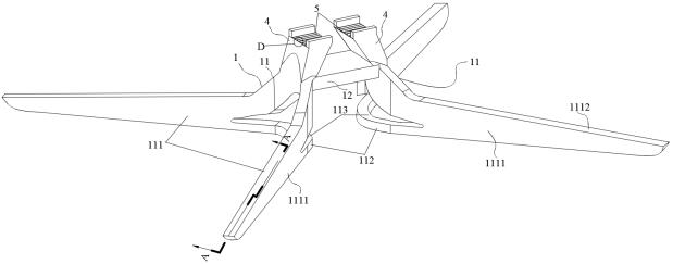
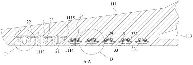
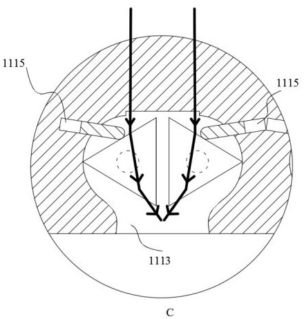
[0036] like Figure 1~7 As shown, a light guide device with gradual extension function includes a fixing device 1, an adjusting device 2, a feedback device 3 and a light incident column 4, the fixing device 1 is connected to the adjusting device 2, the feedback device 3 is connected to the fixing device 1, and the input The light column 4 is tightly connected with the fixing device 1, the fixi...


PUM


Abstract

The invention discloses a light guide device with a gradual change extension function, which comprises a fixing device, an adjusting device, a feedback device and a light incident column, and is characterized in that the fixing device is connected with the adjusting device, the feedback device is connected with the fixing device, the light incident column is fixedly connected with the fixing device, the fixing device comprises a light guide seat, and the light guide seat is fixedly connected with the light incident column; the upper end of the light-in column is provided with a plurality of light-in prisms, the light-in prisms are in light conduction with the light guide seat through the light-in column, the outer side of the light-in column is provided with a light sealing layer, the light guide seat is of a flying wing structure, the light guide seat is provided with a diffusion hole, one end, away from the light-in prisms, of the light-in column is in light conduction with the diffusion hole, and the lower side of the light guide seat is a light-out face. The diffusion part is arranged in an arc shape, light splitting wings are arranged on the two sides of the diffusion part respectively, the diffusion holes are in light conduction with the light splitting wings and the diffusion part respectively, and light convergence is conducted through the light incident prism.

Description

technical field [0001] The invention relates to the technical field of optical elements, in particular to a light guide device with a gradual extension function. Background technique [0002] With the development of science and technology and the continuous popularization of various new products, more and more products use light guide components to improve the appearance or light effect to meet the needs of consumers. [0003] At present, during the use of various optical products, it is often encountered that the installation space is insufficient or the structural position interferes. Therefore, it is necessary to use less light sources to meet more special needs. In this case, the conventional optical structure may not fulfil requirements. [0004] The light source of the light guide device is generally divided into two-end light input or middle light input. The installation of light input at both ends occupies a large area, while the light range of the middle input ligh...

Claims


Application Information

Patent Timeline
IPC IPC(8): G02B6/00
CPCG02B6/00
Inventor 朱伟
Owner 联钢精密科技(中国)有限公司
Why Eureka
Try Eureka