Basket arch concrete pouring equipment for viaduct

A technology for concrete and viaducts, which is applied in bridge construction, erection/assembly of bridges, construction, etc. It can solve the problems of inconvenient dismantling, lower construction efficiency, and heavy volume in the later stage, so as to reduce the workload in the early stage and improve efficiency and volume. small effect

Active Publication Date: 2022-05-17
江苏中车城市发展有限公司 +1
View PDF13 Cites 0 Cited by
  • Summary
  • Abstract
  • Description
  • Claims
  • Application Information

AI Technical Summary

Problems solved by technology

[0002] Viaduct is an important application in modern transportation. It can effectively use the high-rise space in the city or the wilderness and play the role of vehicle diversion. It is an indispensable application method in modern road traffic. In the application process of viaduct, concrete It is an important building material for viaducts. It is not only used for the construction of the main body of the viaduct, but also for the construction of the basket arch. The basket arch is a bridge built on the side of the bridge body like a basket handle in the viaduct system. The sagittal height is very large, which can effectively use the characteristics of the arch to disperse the force of the bridge to the foundation. The bridge body basically does not bear the bending moment and shear force. The construction is carried out in the form of pouring construction, and because some cases are constructed on the river channel, some pipe pile reinforcements are in the river channel, which requires the pouring equipment to have a reliable standing platform to complete the pouring. The existing equipment structure is heavy and bulky Large, it needs to be close to the construction site during pouring, the construction volume in the early stage is huge, and it is inconvenient to withdraw the site in the later stage, which reduces the overall construction efficiency. In view of this, in-depth research on the above problems led to this case

Method used


Image

  • Basket arch concrete pouring equipment for viaduct
  • Basket arch concrete pouring equipment for viaduct
  • Basket arch concrete pouring equipment for viaduct

Examples


Embodiment Construction

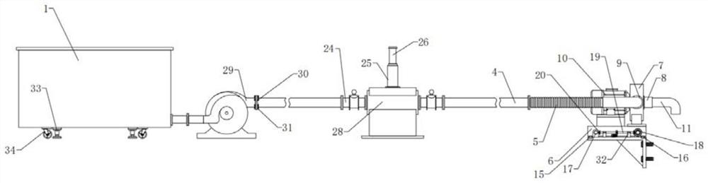
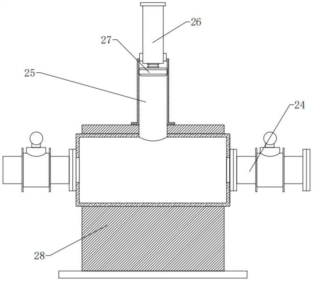
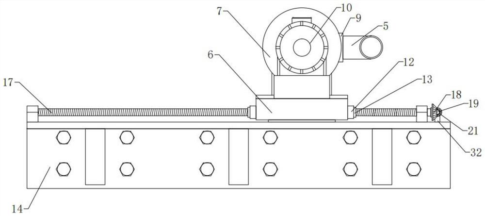
[0029] The present invention is specifically described below in conjunction with accompanying drawing, as Figure 1-5 shown.

[0030] All the electrical components in this case are connected with their corresponding power supply through wires by personnel in the field, and the appropriate controller should be selected according to the actual situation to meet the control requirements. The specific connection and control sequence should refer to the following working principle Among them, the electrical connections between the electrical components are completed sequentially, and the detailed connection methods are well known in the art. The following mainly introduces the working principle and process, and does not explain the electrical control.

[0031] A basket arch concrete pouring equipment for a viaduct, including a base 1, a concrete mixing station 2, a fluid delivery pump 3 and a pipeline connection assembly, the concrete mixing station 2 is installed on the base 1, an...


PUM


Abstract

The basket arch concrete pouring equipment comprises a base, a concrete mixing plant, a fluid conveying pump and a pipeline connecting assembly, the concrete mixing plant is installed on the base, the fluid conveying pump is installed on one side of the concrete mixing plant, and the basket arch concrete pouring equipment is characterized in that a discharging port is formed in the end of the fluid conveying pump; an extending conveying material pipe is connected to the discharging opening, and the fluid conveying pump is connected with a pipeline connecting assembly arranged at the end of the extending conveying material pipe; the basket arch concrete pouring equipment for the viaduct has the beneficial effects that the problem that the deployment workload of concrete pouring equipment is large in the basket arch pouring process of an existing viaduct is solved, and the conveying distance is increased in a multi-section relay mode; and meanwhile, a cyclic concrete pouring mechanism can be driven to pour the basket arch, the size is small, the site requirement can be effectively reduced, the basket arch pouring efficiency is improved, and the early-stage workload of construction is reduced.

Description

technical field [0001] The invention relates to the technical field of concrete pouring equipment, in particular to basket arch concrete pouring equipment for viaducts. Background technique [0002] Viaduct is an important application in modern transportation. It can effectively use the high-rise space in the city or the wilderness and play the role of vehicle diversion. It is an indispensable application method in modern road traffic. In the application process of viaduct, concrete It is an important building material for viaducts. It is not only used for the construction of the main body of the viaduct, but also for the construction of the basket arch. The basket arch is a bridge built on the side of the bridge body like a basket handle in the viaduct system. The sagittal height is very large, which can effectively use the characteristics of the arch to disperse the force of the bridge to the foundation. The bridge body basically does not bear the bending moment and shear ...

Claims


Application Information

Patent Timeline
Patent Type & Authority Applications(China)
IPC IPC(8): E01D21/00E01D101/24
CPCE01D21/00E01D2101/24
Inventor 王礼武钱栋栋刘德欣赵海川丁远振
Owner 江苏中车城市发展有限公司
Why Eureka
Try Eureka