Tool arranged on press machine and used for forging wind power flange blank and punching through center hole
A technology for wind power flanges and presses, which is applied in the direction of piercing presses, manufacturing tools, sustainable manufacturing/processing, etc. It can solve the problems of unable to clamp flanges and quickly change the face of flanges, etc., to achieve Easy to place, ensure accuracy, and avoid pollution
- Summary
- Abstract
- Description
- Claims
- Application Information
AI Technical Summary
Problems solved by technology
Method used
Image
Examples
Embodiment 1
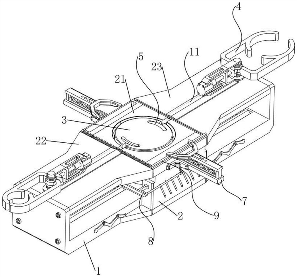
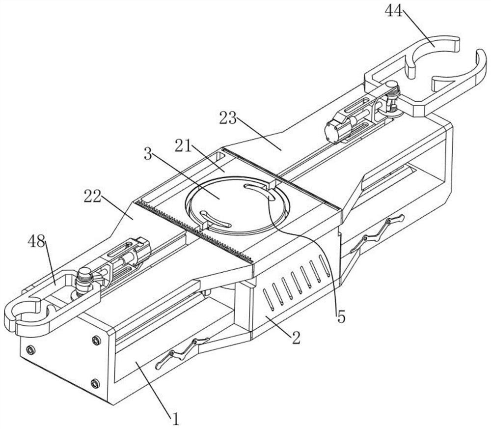
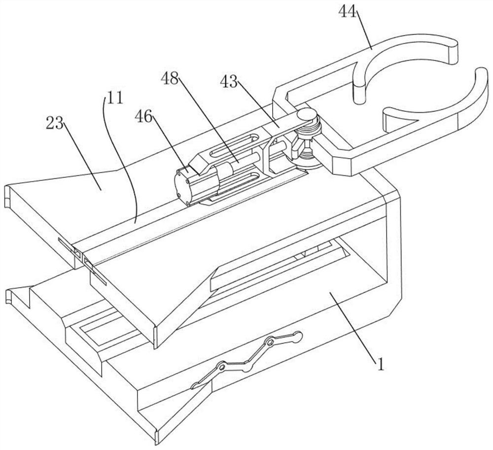
[0040] A tool for punching through the central hole of a forged wind power flange blank on a press, such as figure 1 , figure 2 , image 3 , Figure 4 , Figure 5 , Figure 10 and Figure 11 As shown, it includes a base plate 1, a support plate 2, a mounting plate 21, a first fixed plate 22, a second fixed plate 23, a forging table 3, a clamping mechanism 4, a turning mechanism 5 and a rotating mechanism 6. The upper side of the middle part of the base plate 1 The support plate 2 is bolted symmetrically front and rear at the eccentric position, and a mounting plate 21 is welded between the upper parts of the two support plates 2, and a first fixing plate 22 and a second fixing plate 22 are respectively bolted between the left and right sides of the mounting plate 21 and the bottom plate 1. Plate 23, a forging table 3 is welded on the upper side of the middle of the bottom plate 1, the forging table 3 runs through the mounting plate 21, a clamping mechanism 4 is arranged ...
Embodiment 2
[0046] On the basis of Example 1, such as figure 1 , Figure 6 and Figure 7 As shown, it also includes a correction mechanism 7, the correction mechanism 7 includes a guide rail plate 71, a slider 72 and a correction plate 73, the front and rear sides of the mounting plate 21 are symmetrically welded with a guide rail plate 71, and the slide type is provided with a slide Block 72 , an elastic member 74 is connected between the slider 72 and the mounting plate 21 , and a correcting plate 73 is bolted symmetrically on the opposite side of the two sliders 72 .
[0047] Such as figure 1 , Figure 8 , Figure 9 and Figure 12 As shown, auxiliary mechanism 8 is also included, and auxiliary mechanism 8 includes first wire rope 81, first conduit 82, second connecting rod 83, guide plate 84, pull plate 85, hinge plate 86, second torsion spring 87, stop Plate 88, the second back-moving spring 89 and extruding plate 810, the first guide tube 82 is welded symmetrically on the side ...
Embodiment 3
[0050] On the basis of Example 2, such as figure 1 , Figure 8 , Figure 13 and Figure 14 As shown, scraping mechanism 9 is also included, and scraping mechanism 9 includes scraping plate 91, second steel wire rope 92, high temperature resistant spring 93, second conduit 94, magnetic block 95 and magnetic ring 96, and the right rear of mounting plate 21 There is a second conduit 94 through the upper part of the mounting plate 21. A scraper plate 91 is slidingly provided on the upper side of the front of the mounting plate 21. A high temperature resistant spring 93 is connected between the rear side of the left part of the scraping plate 91 and the mounting plate 21. The right side of the scraping plate 91 The rear side of the part is connected with a second steel rope 92, and the second steel rope 92 slides through the second conduit 94. The tail end of the second steel rope 92 is connected with a magnetic block 95, and the middle part of the first connecting rod 42 on the ...
PUM
 Abstract
Description
Claims
Application Information
 - R&D Engineer
- R&D Manager
- IP Professional
- Industry Leading Data Capabilities
- Powerful AI technology
- Patent DNA Extraction
Browse by: Latest US Patents, China's latest patents, Technical Efficacy Thesaurus, Application Domain, Technology Topic, Popular Technical Reports.
© 2024 PatSnap. All rights reserved.Legal|Privacy policy|Modern Slavery Act Transparency Statement|Sitemap|About US| Contact US: help@patsnap.com


