
Antenna patch, patch antenna, antenna array and electronic equipment

A technology for electronic equipment and patch antennas, applied to antenna arrays, individually powered antenna arrays, antennas, etc., can solve the problems of affecting the pattern, mismatch, narrow bandwidth, etc., to reduce the size of the antenna, improve the matching degree, reduce the The effect of loss

Active Publication Date: 2022-05-13
NANJING FORESTRY UNIV +1
View PDF5 Cites 0 Cited by
  • Summary
  • Abstract
  • Description
  • Claims
  • Application Information

AI Technical Summary

Problems solved by technology

However, in the high frequency band, such as the millimeter wave frequency band, the redundant branch can also be regarded as a resonant unit, which is likely to cause unwanted radiation and affect the pattern
However, the matching network constructed by lumped parameter components either has no devices corresponding to the frequency band, or has a narrow bandwidth and is too sensitive to the frequency band, resulting in poor matching performance.
[0003] In the prior art, there is a method of directly slotting the patch antenna unit itself to match it. However, due to the limitation of the geometric size of the patch itself in the millimeter wave frequency band, in order to achieve the required slot length, it is usually necessary to bend the slotted wiring , which will result in various parasitic capacitances between the bent traces, such as Figure 9 C1, C2, and C3 shown in , which lead to the excessive value of the single capacitive component in the antenna matching process, resulting in mismatch and difficult adjustment to a satisfactory matching result

Method used


Image

  • Antenna patch, patch antenna, antenna array and electronic equipment
  • Antenna patch, patch antenna, antenna array and electronic equipment
  • Antenna patch, patch antenna, antenna array and electronic equipment

Examples


Embodiment Construction

[0026] The technical solutions in the embodiments of the present application will be clearly and completely described below in conjunction with the drawings in the embodiments of the present application. Apparently, the described embodiments are only some of the embodiments of this application, not all of them. Based on the embodiments in this application, all other embodiments obtained by those skilled in the art without making creative efforts belong to the scope of protection of this application.

[0027] In the description of this application, it should be noted that unless otherwise specified and limited, the terms "installation", "connection", and "connection" should be understood in a broad sense, for example, it can be a fixed connection or a detachable connection. Connected, or integrally connected; it can be mechanically connected, or electrically connected, or can communicate with each other; it can be directly connected, or indirectly connected through an intermedi...


PUM


Abstract

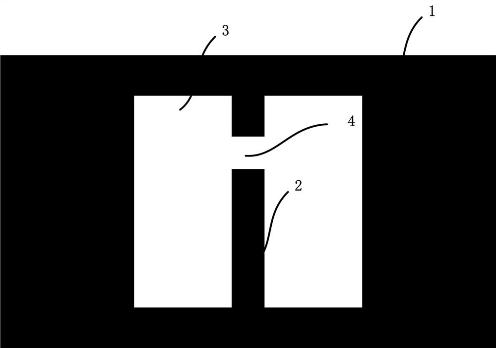
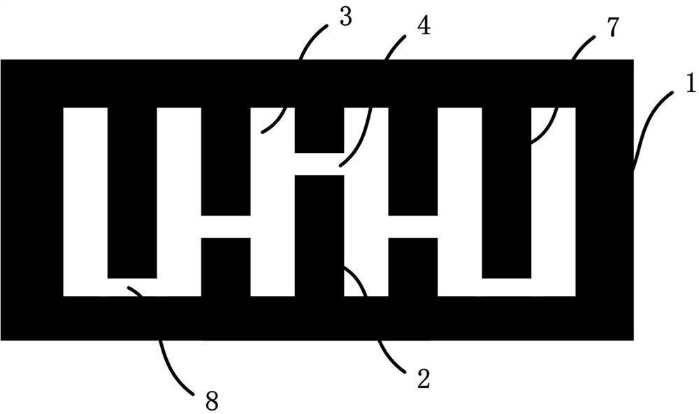
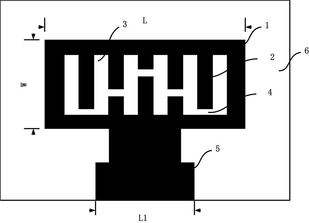
The invention discloses an antenna patch, a patch antenna, an antenna array and electronic equipment, and the antenna patch comprises a patch body which is internally provided with an opening; at least one first conductor is arranged in the open hole along the vertical direction, and at least one open slot for dividing the first conductor into two or more sections is formed in each first conductor; the slots of the adjacent first conductors are not on the same horizontal line. According to the patch antenna, the matching degree is improved, loss is reduced, additional arrangement of a matching branch knot or a matching circuit is not needed, and the geometric dimension of the antenna radiation unit is directly adjusted.

Description

technical field [0001] The invention relates to the field of electronic technology, in particular to an antenna patch, a patch antenna, an antenna array and electronic equipment. Background technique [0002] The matching of the microstrip patch antenna is usually matched by an open or short-circuit stub at the feeder end, or a matching network with lumped parameters is designed in the feeder circuit. However, in the high-frequency band, such as the millimeter-wave frequency band, the redundant branch can also be regarded as a resonant unit, which is likely to cause unwanted radiation and affect the pattern. However, the matching network constructed by lumped parameter components either has no devices corresponding to the frequency band, or has a narrow bandwidth and is too sensitive to the frequency band, resulting in poor matching performance. [0003] In the prior art, there is a method of directly slotting the patch antenna unit itself to match it. However, due to the l...

Claims


Application Information

Patent Timeline
Patent Type & Authority Applications(China)
IPC IPC(8): H01Q1/38H01Q1/50H01Q21/00H01Q21/08H01Q1/22
CPCH01Q1/38H01Q1/50H01Q21/0006H01Q21/08H01Q1/22
Inventor 陶子健冯友怀
Owner NANJING FORESTRY UNIV
Learn More