Assembly of electrode frame and diaphragm of flow battery and application
A liquid flow battery and electrode frame technology, which is applied to fuel cell parts, fuel cells, electrical components, etc., can solve problems such as battery leakage, and achieve the effects of improving reliability, broadening application methods, and reducing volume
- Summary
- Abstract
- Description
- Claims
- Application Information
AI Technical Summary
Problems solved by technology
Method used
Image

Examples
Embodiment 1
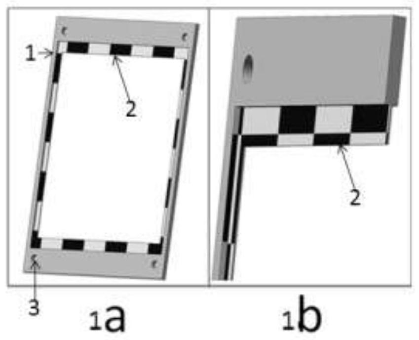
[0024] Select a square polyethylene flat plate as the base material of the ring-shaped electrode frame 1 with a through hole in the middle, which is 600 mm long, 400 mm wide, and 8 mm thick; flow channels 3 are respectively arranged on the two side surfaces of the electrode frame 1 (respectively) As the electrolyte inlet and outlet flow channels, the electrolyte inlet flow channel and outlet flow channel on each side surface of the electrode frame are set on the opposite surface of the through hole on each side surface of the electrode frame); the electrode frame through hole (length 500mm, width 300mm) There is an annular platform 2 in the middle (the central axis of geometric symmetry with the through hole). The thickness of the annular platform 2 is 1 mm and the electrode frame 1 is evenly divided into two parts. Each part has a thickness of 3.5 mm and is respectively Place the positive and negative terminals of the battery. as attached figure 1 shown in the attached figu...
Embodiment 2
[0026] Select a square polyethylene flat plate as the base material of the ring-shaped electrode frame 1 with a through hole in the middle, which is 600 mm long, 400 mm wide, and 8 mm thick; flow channels 3 are respectively arranged on the two side surfaces of the electrode frame 1 (respectively) As the electrolyte inlet and outlet flow channels, the electrolyte inlet flow channel and outlet flow channel on each side surface of the electrode frame are set on the opposite surface of the through hole on each side surface of the electrode frame); the electrode frame through hole (length 500mm, width 300mm) There is an annular platform 2 in the middle (the central axis of geometric symmetry with the through hole). The thickness of the annular platform 2 is 1 mm and the electrode frame 1 is evenly divided into two parts. Each part has a thickness of 3.5 mm and is respectively Place the positive and negative terminals of the battery. as attached figure 1 shown in the attached figu...
Embodiment 3
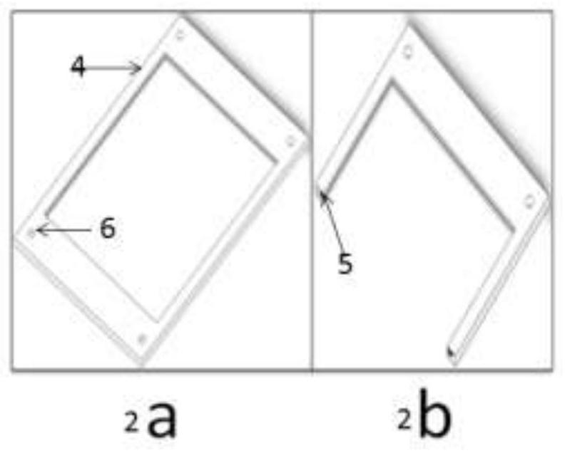
[0028] Choose a square polyethylene flat plate as the base material of the ring-shaped electrode frame 4 with a through hole in the middle, which is 600 mm long, 400 mm wide, and 8 mm thick; flow channels 6 are respectively arranged on the two side surfaces of the electrode frame 4 (respectively) As the electrolyte inlet and outlet flow channels, the electrolyte inlet flow channel and outlet flow channel on each side surface of the electrode frame are set on the opposite surface of the through hole on each side surface of the electrode frame); the electrode frame through hole (length 500mm, width 300mm) An annular groove 5 is arranged in the middle (the same geometrically symmetrical central axis as the through hole), the thickness of the annular groove 5 is 400um and the electrode frame 4 is evenly divided into two parts, each part has a thickness of 3.8mm, and Place the positive and negative poles of the battery inside. as attached figure 2 shown in the attached figure 2...
PUM
| Property | Measurement | Unit |
|---|---|---|
| thickness | aaaaa | aaaaa |
| thickness | aaaaa | aaaaa |
| thickness | aaaaa | aaaaa |
Abstract
Description
Claims
Application Information
 - R&D
- Intellectual Property
- Life Sciences
- Materials
- Tech Scout
- Unparalleled Data Quality
- Higher Quality Content
- 60% Fewer Hallucinations
Browse by: Latest US Patents, China's latest patents, Technical Efficacy Thesaurus, Application Domain, Technology Topic, Popular Technical Reports.
© 2025 PatSnap. All rights reserved.Legal|Privacy policy|Modern Slavery Act Transparency Statement|Sitemap|About US| Contact US: help@patsnap.com