
Integrated reagent detection tube and detection method thereof

A detection tube and reagent tube technology, applied in the field of detection devices, can solve the problems of high reagent cost, low-temperature storage of reagents, insufficient detection flux, etc., and achieve the effects of improving sensitivity, accelerating reaction speed, and simplifying reagent structure

Pending Publication Date: 2022-05-13
XIAMEN XIANMING BIOTECH CO LTD
View PDF1 Cites 0 Cited by
  • Summary
  • Abstract
  • Description
  • Claims
  • Application Information

AI Technical Summary

Problems solved by technology

This type of reagent simplifies the structure of the instrument to a certain extent, but there are also disadvantages such as insufficient detection flux, high reagent cost, and the need to store reagents at low temperature.

Method used


Image

  • Integrated reagent detection tube and detection method thereof
  • Integrated reagent detection tube and detection method thereof
  • Integrated reagent detection tube and detection method thereof

Examples


Embodiment 1

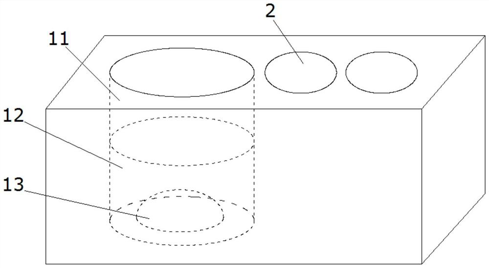
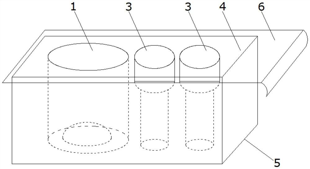
[0059] Such as Figure 1-3 An integrated reagent detection tube is shown, including Figure 5 The solid phase microtube 1 composed of 1123A or 1123B, or 1123C rotating body bottom 13 spherical segments in the internal solid phase microtube 1A.

[0060] Such as Figure 5 As shown, the upper part 11 and the lower part 12 of the solid-phase microtube 1A have a cylindrical structure, and the bottom 13 adopts 1123A, 1123B, or 1123C spherical segments to form a structure that increases the surface area of ​​the cavity and projects upwards, which is consistent with The cooperation of the lower part 12 can further reflect the light to the top detector.

[0061] The upper part 11, the lower part 12 and the bottom 13 of the cylindrical structure are formed by 1123A or 1123B or 1123C spherical segments. The solid-phase microtube 1 together with the bracket 4 and the base 5 are pre-immobilized with the target detection substance reaction component antigen or antibody.

[0062] The bott...

Embodiment 2

[0070] Such as Figure 1 ~ Figure 3 An integrated reagent detection tube is shown, including Figure 7 Solid phase microtube 1 composed of 1123B or 1123C, or 1122C rotator, or 1121C, or 1121D prism plus 11 cylinders at the top and 12 rounded 1F at the bottom of the inner solid microtube 1D structure.

[0071] Such as Figure 7 As shown, the body of the solid-phase microtube 1 of the present invention is a cylinder with an upper part 11 and a rounded platform 1F structure with a lower part 12, and the bottom 13 is a structure formed by 1123B, or 1123C, or 1122C rotating body, or 1121C, or 1121D prism, It has the effect of increasing the surface area of ​​the cavity and projecting upwards, and can further reflect light to the top detector by cooperating with the lower part 12, increasing the solid-liquid reaction interface of the immune reaction liquid, accelerating the progress of the immune reaction, shortening the detection time, and improving and ensuring Improve the detec...


PUM


Abstract

The invention discloses an integrated reagent detection tube and a use method thereof. The integrated reagent detection tube comprises a mounting bracket provided with a plurality of mounting holes; the solid-phase microtube is arranged in the bracket and comprises an upper part, a lower part and a bottom part arranged on the bottom surface of the inner side of the lower part, the lower part extends from the upper part to the lower end and is gradually narrowed, and the bottom part extends upwards from the bottom surface of the inner side of the lower part and is gradually narrowed; the reagent tubes are provided with markers, and the reagent tubes are arranged in the mounting holes; the sealing film covering the tops of the solid-phase microtube and the reagent tube continuously narrows the lower part and the bottom of the solid-phase microtube, so that the specific surface area of a microtube reaction area and the total upward projection surface area of the lower part of the microtube are fully increased while signal generation is not affected, and optical signals formed by upward projection of reaction products by the microtube are increased; further, the detection sensitivity is improved, the reaction speed is accelerated, and a reaction container and a reaction medium for detecting the reagent can be quickly established.

Description

technical field [0001] The invention relates to a detection device, in particular to an integrated reagent detection tube and a detection method thereof. Background technique [0002] So far, immunoassay technology has developed towards full automation, high sensitivity, both high and low throughput, and easy operation. [0003] Fully automatic chemiluminescent immunoassay technology plays a central role in modern clinical immunological detection methods because of its high sensitivity, good stability and flexible operation on automated equipment. Bioactive substances or diseases related to human physiology and pathology Markers, as well as foreign antigens, can be used to achieve micro-quantitative detection, which can be used for disease diagnosis, curative effect evaluation and prognosis judgment. [0004] Due to the multi-component characteristics of the reagents on the automatic chemiluminescence immunoassay analyzer, the fully automatic detection system developed toda...

Claims


Application Information

Patent Timeline
Patent Type & Authority Applications(China)
IPC IPC(8): G01N33/543G01N33/58
CPCG01N33/5304G01N33/54313G01N33/582
Inventor 徐恩良吴凤霞徐高扬
Owner XIAMEN XIANMING BIOTECH CO LTD
Learn More