Eureka AIR delivers breakthrough ideas for toughest innovation challenges, trusted by R&D personnel around the world.

Optical amplifiers in a free space laser communication system

a laser communication system and optical amplifier technology, applied in the field of optical amplifiers in a free space laser communication system, can solve the problems of inability to communicate data at fiber optic speeds, high cost of inability to achieve e-o and o-e conversion, so as to reduce the diameter of the amplified attenuated optical signal and reduce the diameter of the amplified optical signal

Active Publication Date: 2006-11-14
XYLON LLC
View PDF30 Cites 8 Cited by
  • Summary
  • Abstract
  • Description
  • Claims
  • Application Information

AI Technical Summary

Benefits of technology

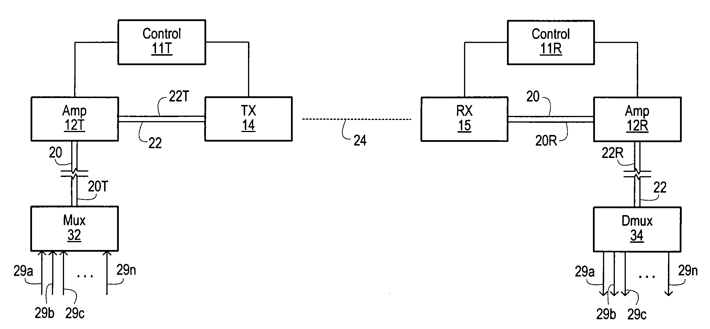
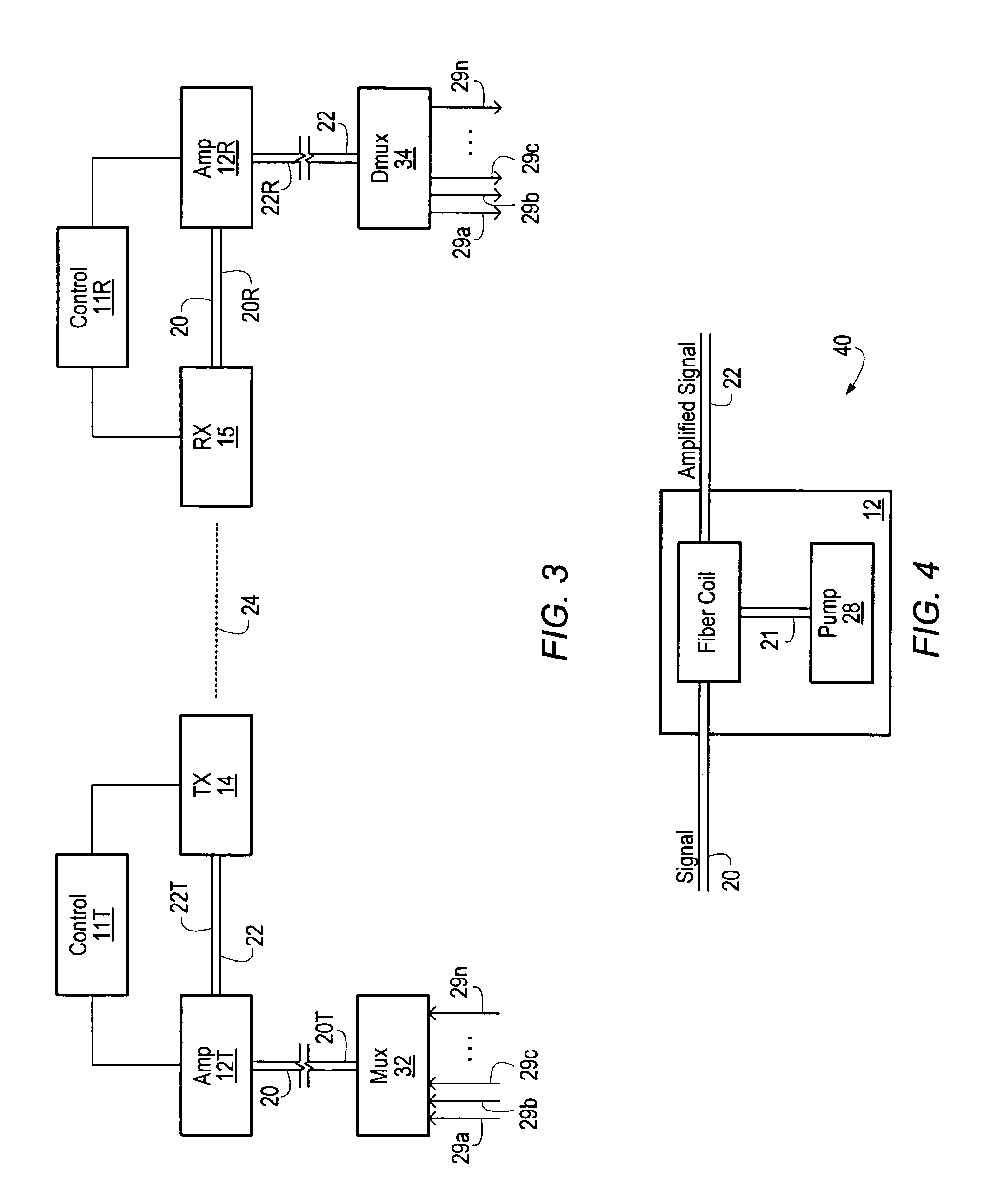
[0015]In another embodiment, the free space optical communication system may further comprise a receiver for receiving the optical signal and an optical amplifier configured to amplify the attenuated optical signal. In addition, the system may include an adiabatic taper apparatus coupled to the receiver and configured to reduce the diameter of the attenuated optical signal. In one embodiment, the adiabatic taper apparatus reduces the diameter of the amplified attenuated optical signal by a factor of about five.

Problems solved by technology

In other words, even if the backbone of the network is high speed fiber optic, the end user connection using a telephone line, for example, cannot communicate the data at the fiber optic speeds.
In practice, however, optical signals experience attenuation as they travel across a transmission medium.
These E-O and O-E conversions are expensive and cause the system to have increased complexity.

Method used


Image

  • Optical amplifiers in a free space laser communication system
  • Optical amplifiers in a free space laser communication system
  • Optical amplifiers in a free space laser communication system

Examples


Embodiment Construction

[0032]The following presents a detailed description of embodiments of the invention. However, the invention can be embodied in a multitude of different ways as defined and covered by the claims. The invention is more general than the embodiments that are explicitly described, and is not limited by the specific embodiments but rather is defined by the appended claims.

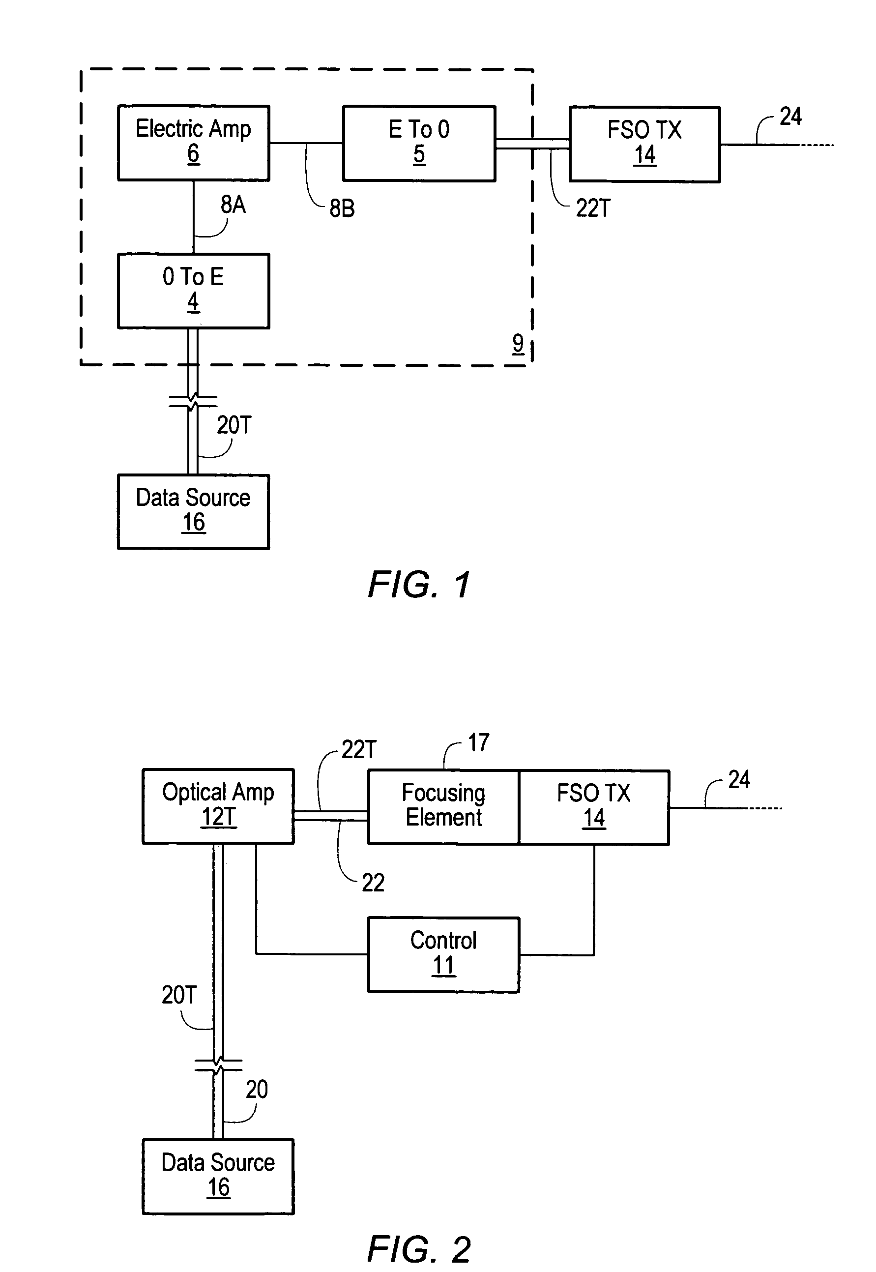
[0033]FIG. 2 is a block diagram illustrating a transmitter portion of a FSO system. Data source 16 represents the optical transmission point where the data is transmitted on to a fiber optic line. Data source 16 may include a router, switching node, server, or even an individual PC with an optical modem. As the optical signal 20T, from data source 16, is transmitted across a long-haul network, the optical signal encounters some signal attenuation, interference, scattering, and reflections. After some distance the optical signal may be too weak to accurately transmit into free space. Therefore, the optical signal must be ...


PUM


Abstract

Disclosed is a novel free space optical communication system comprising an optical amplifier configured to amplify an optical signal received from a fiber optic cable, a transmitter coupled to the optical amplifier and configured to transmit the amplified optical signal across a free space medium. The system also includes a receiver configured to receive the attenuated optical signal and a second optical amplifier coupled to the receiver configured to amplify the attenuated optical signal before transmitting the optical signal on to a fiber optic cable. The optical amplifier is preferably a Raman optical amplifier, but may also be any other optical amplifier, or combination of optical amplifiers, known in the art.

Description

BACKGROUND OF THE INVENTIONDescription of the Related Art[0001]Communication through the use of optical signals is becoming increasingly prevalent in modern communication systems. In particular, the widespread use of fiber optic cables has reduced the cost and complexity of transmitting optical data, while making substantial advances in the bandwidth available to individual users. Indeed, fiber optic wire carries much more information than conventional copper wire and is far less subject to electromagnetic interference.[0002]Recent advances in optical signal multiplexing have further increased the amount of data that may be transmitted on a single optical fiber. For example, Dense wavelength division multiplexing (“DWDM”) is a technique that puts data from different sources together on an optical fiber, with each signal carried at the same time on its own separate light wavelength. Using current DWDM techniques, up to 80 (and theoretically more) separate wavelengths or channels of d...

Claims


Application Information

Patent Timeline
Patent Type & Authority Patents(United States)
IPC IPC(8): H04B10/08H04B10/10
CPCH04B10/112
Inventor BLOOM, SCOTT HARRIS
Owner XYLON LLC
Why Eureka
Eureka Blog
Learn More