
Shading adhesive tape backlight module side wall automatic attaching equipment

A technology of backlight module and shading tape, applied in optics, nonlinear optics, instruments, etc., can solve problems such as difficulty in meeting automated production requirements, dislocation, and inconsistent thickness of backlight modules, and achieve the goal of improving automated production accuracy and production efficiency. Effect

Pending Publication Date: 2022-05-10
广东立迪智能科技有限公司
View PDF0 Cites 2 Cited by
  • Summary
  • Abstract
  • Description
  • Claims
  • Application Information

AI Technical Summary

Problems solved by technology

[0003] In the production of mobile phones, computers, tablets, etc., it is necessary to attach the light-shielding tape to the side wall of the backlight module. The existing production method is manual attachment, the process is cumbersome, and the attachment speed is slow, which is difficult to meet the needs of automated production; and manual The attachment method of attachment is prone to deviation or misalignment, which affects the yield of the product
Of course, there are also automated mechanical equipment, but they have the problems of poor automation stability and poor fitting accuracy.
Among them, the attachment method of the side wall has inconsistent thickness of the backlight module, and the attachment and fixation are relatively unstable.

Method used


Image

  • Shading adhesive tape backlight module side wall automatic attaching equipment
  • Shading adhesive tape backlight module side wall automatic attaching equipment
  • Shading adhesive tape backlight module side wall automatic attaching equipment

Examples


Embodiment Construction

[0032] The technical solutions in the embodiments of the present invention will be clearly and completely described below in conjunction with the accompanying drawings. Apparently, the described embodiments are only part of the embodiments of the present invention, not all of them. Based on the embodiments of the present invention, all other embodiments obtained by persons of ordinary skill in the art without creative efforts fall within the protection scope of the present invention.

[0033] It should be noted that if there are directional indications (such as up, down, left, right, front, back, top, bottom, inside, outside, vertical, horizontal, vertical, counterclockwise, clockwise, circumferential) in the embodiment of the present invention direction, radial direction, axial direction...), the directional indication is only used to explain the relative positional relationship, movement conditions, etc. When a change occurs, the directional indication changes accordingly. ...


PUM


Abstract

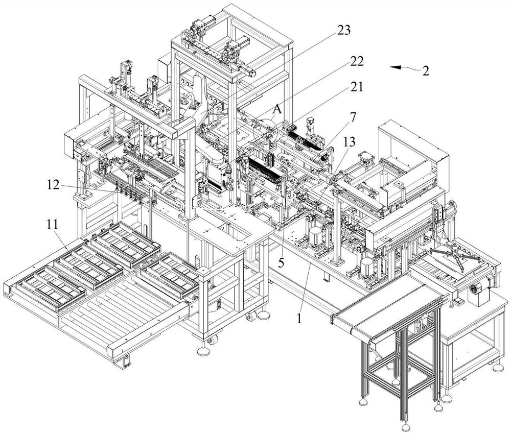
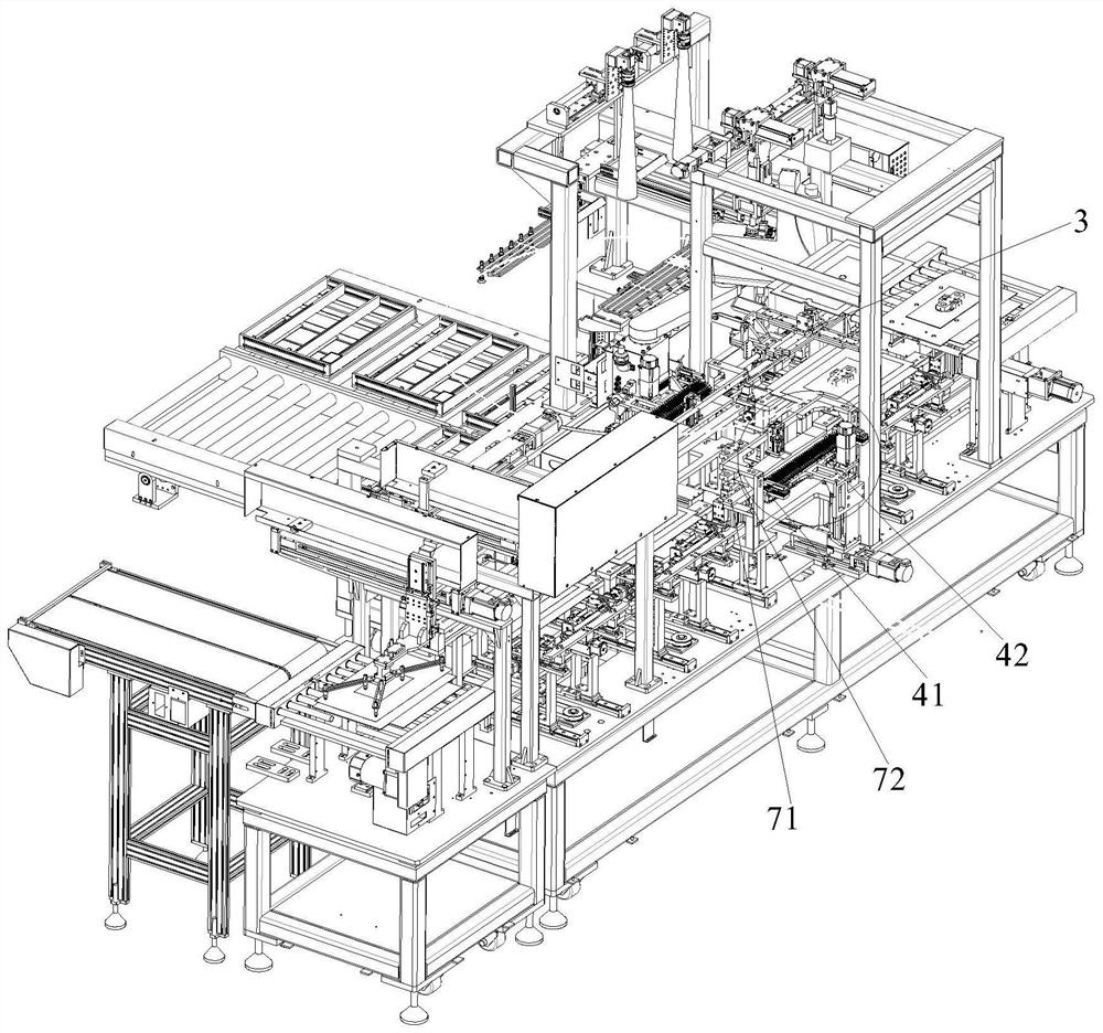
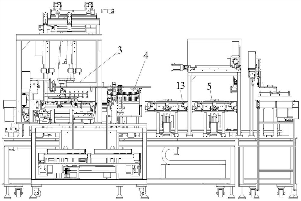
The invention discloses shading adhesive tape backlight module side wall automatic attaching equipment which comprises a rack, a feeding device, a clamping device, a correcting device, an attaching grabbing device, a film tearing device, a rotating device, a pressing and attaching device and a detecting device. The film tearing device is arranged at the lower end of the attaching device and used for removing a protective film of the shading adhesive tape. A plurality of backlight modules can be placed at the same time through the feeding device, automatic attachment of the assembly line type backlight modules is achieved, reference points of the backlight modules are adjusted through the correction device of the attachment device, and then adhesive tape attachment on the four side walls of the attachment device is achieved through cooperation of the attachment device and the rotating device. And the film tearing device and the rotating device are matched to remove the protective films of the adhesive tapes on the four side walls at one station, and the adhesive tapes are pressed and pasted through the pressing and pasting device in the next working procedure, so that one-time pasting is realized, and the automatic production precision and the production efficiency are improved.

Description

technical field [0001] The invention relates to the field of liquid crystal display processing equipment, in particular to an automatic attachment equipment for the side wall of a backlight module with a light-shielding tape. Background technique [0002] The backlight module is one of the key components of the LCD panel. The function is to supply sufficient brightness and evenly distributed light source so that it can display images normally. The backlight is the light source that provides the LCD panel. It is mainly composed of light source, light guide plate, optical film, plastic frame and so on. The backlight has the characteristics of high brightness, long life and uniform light emission. Light-shielding tape, that is, the tape used to achieve light blocking, is mainly suitable for fixing LCD panels and backlight modules in electronic equipment and various light-shielding applications. Minimize the impact of light in applications that require controlled brightness....

Claims


Application Information

Patent Timeline
Patent Type & Authority Applications(China)
IPC IPC(8): G02F1/13
CPCG02F1/1303
Inventor 戴燕舞
Owner 广东立迪智能科技有限公司
Learn More