
Garden assembly type rest sentry box

A prefabricated and garden technology, applied to other seating furniture, building types, buildings, etc., can solve the problems of low comfort, easy to catch cold, people feel cold, etc., and achieve the effect of comfortable rest, simple structure and uniform force

Inactive Publication Date: 2022-05-10
ZHEJIANG COLLEGE OF CONSTR
View PDF0 Cites 0 Cited by
  • Summary
  • Abstract
  • Description
  • Claims
  • Application Information

AI Technical Summary

Problems solved by technology

[0002] Most of the existing garden rest sentry boxes are made of concrete base, and cement or wood pillars are installed on it, and then the corresponding ceiling is installed to form a building structure that can shelter from wind and rain for people to rest. The disadvantage of the sentry box is that first of all, when the sentry box is sheltered from the wind and rain, it is inevitable that there will be wind and passing through it. At this time, when the personnel are resting, they will be blown by the wind and rain, causing the personnel to feel cold and easy to catch cold, and correspondingly The sentry box cannot be assembled during the construction process, which makes the process of manufacturing the sentry box more troublesome. Secondly, most of the seats in the existing sentry box are fixed seats, which cannot adjust the distance between each other. The comfort level is low when sitting or lying down. Due to the existence of the above problems, it is extremely inconvenient to use and build the existing sentry box

Method used


Image

  • Garden assembly type rest sentry box
  • Garden assembly type rest sentry box
  • Garden assembly type rest sentry box

Examples


Embodiment Construction

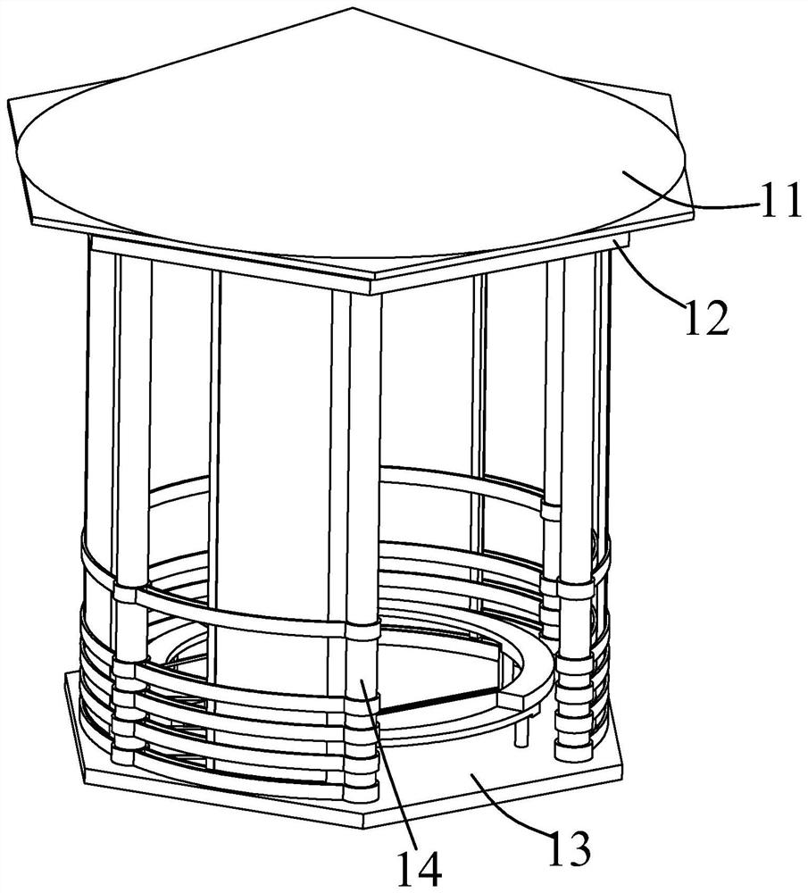
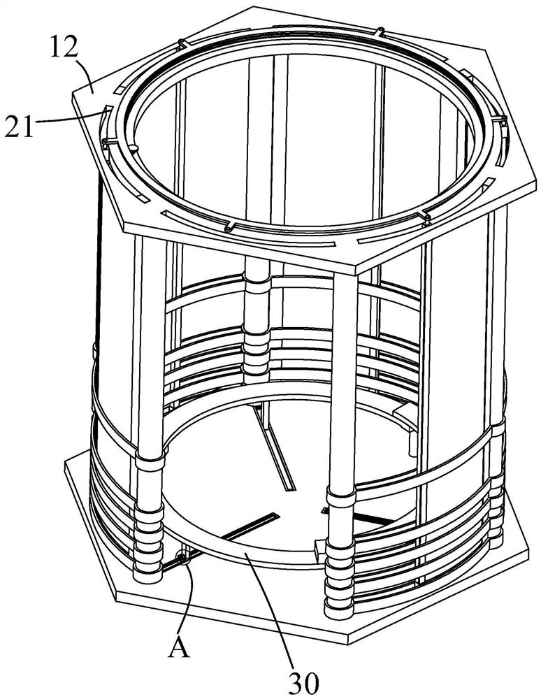
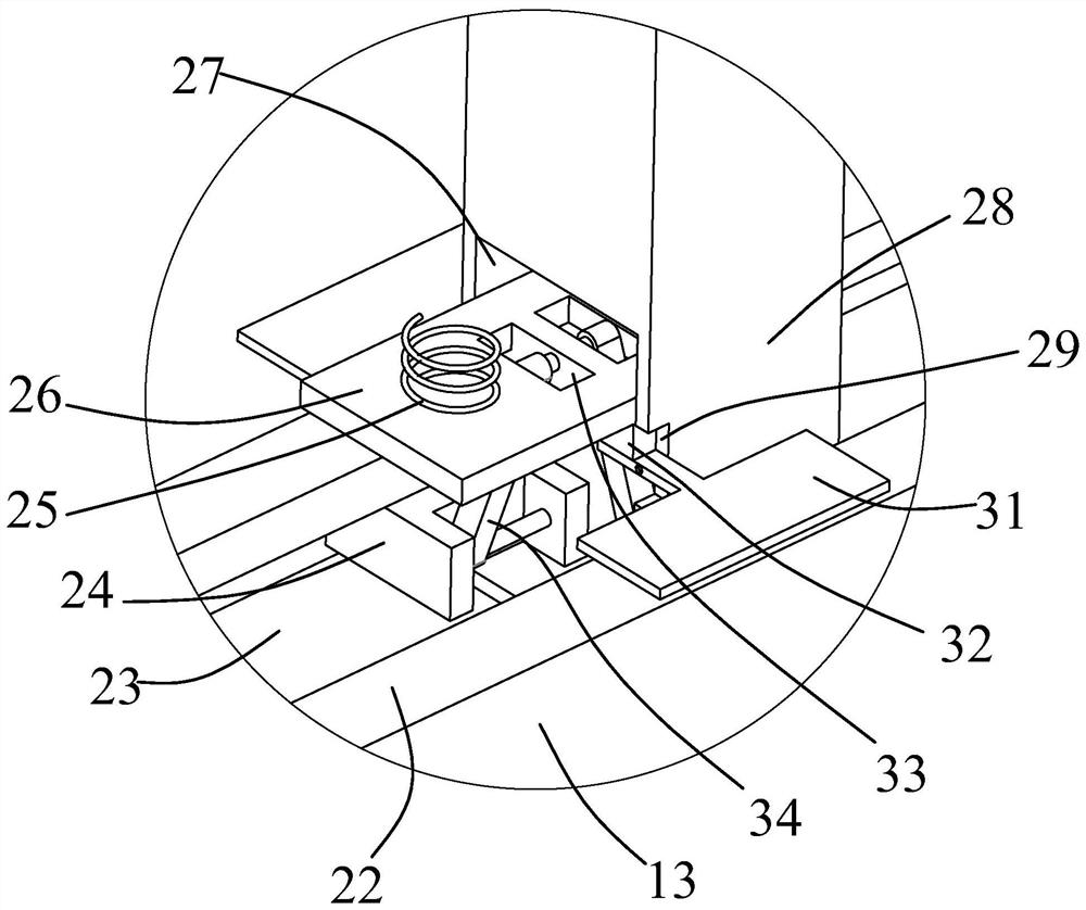
[0030] Such as Figure 1-Figure 12 As shown, the present invention is described in detail. For the convenience of description, the orientations mentioned below are now stipulated as follows: figure 1 The up, down, left, right, front and back directions of the projection relationship itself are consistent. The garden assembly type rest sentry box of the present invention includes a bottom side plate 13 and a top side plate 12. A number of uprights 14 are fixedly arranged between the boards 13, and several mating sleeves 41 are arranged on the outer surfaces of the uprights 14 to slide, and fence boards 42 are fixedly arranged between the mating sleeves 41, and the upper and lower adjacent fence boards 42 are hingedly provided with Side articulated rod 43, the side articulated rod 43 that is positioned at fence board 42 sides forms fork structure, bottom side plate 13 top and top side plate 12 bottoms are provided with mating connecting seat 47, and the hinge point between side ...


PUM


Abstract

The garden assembly type rest sentry box comprises a bottom side plate and a top side plate, a top cover is arranged at the top of the bottom side plate in a clamped mode, a plurality of stand columns are fixedly arranged between the top side plate and the bottom side plate, a plurality of matching sleeves are slidably arranged on the outer surfaces of the stand columns, and fence plates are fixedly arranged between the matching sleeves; side hinge rods are hinged between the upper and lower adjacent fence plates, matched connecting bases are arranged at the tops of the bottom side plates and the bottoms of the top side plates, middle columns are rotatably arranged in the matched connecting bases, connecting wheels are rotatably arranged on the two sides of each middle column, connecting grooves are formed in the connecting wheels, and the connecting grooves are connected with the bottom side plates. According to the equipment, the positions of the seats can be adjusted, when the seats are arranged in a staggered mode, stress is uniform, meanwhile, people can sit and lie more conveniently, the equipment can form a wrapping structure on the outer surface of the sentry box to keep out wind and rain, and people can have a rest more comfortably.

Description

technical field [0001] The invention relates to the technical field of garden sentry box equipment, in particular to an assembled garden rest sentry box. Background technique [0002] Most of the existing garden rest sentry boxes are made of concrete base, and cement or wood pillars are installed on it, and then the corresponding ceiling is installed to form a building structure that can shelter from wind and rain for people to rest. The disadvantage of the sentry box is that first of all, when the sentry box is sheltered from the wind and rain, it is inevitable that there will be wind and passing through it. At this time, when the personnel are resting, they will be blown by the wind and rain, causing the personnel to feel cold and easy to catch cold, and correspondingly The sentry box cannot be assembled during the construction process, which makes the process of manufacturing the sentry box more troublesome. Secondly, most of the seats in the existing sentry box are fixed...

Claims


Application Information

Patent Timeline
IPC IPC(8): E04H1/12E04F10/04A47C7/00A47C7/02
CPCE04H1/1205E04F10/04A47C7/002A47C7/02
Inventor 厉子强沈玉英施纳新卢山邱希阳
Owner ZHEJIANG COLLEGE OF CONSTR
Learn More