
Adjustable cast-in-place support platform for pouring steel-concrete composite beam cantilever top plate

A technology of steel-concrete composite beams and support platforms, which is applied to buildings, bridges, bridge materials, etc., can solve the problems of high construction safety risks, unsecured construction personnel safety, and high safety risks, so as to improve spraying efficiency and spraying effect. , convenient for multi-directional spraying, and the effect of improving safety

Pending Publication Date: 2022-05-10
CCCC FIRST HIGHWAY XIAMEN ENG
View PDF0 Cites 0 Cited by
  • Summary
  • Abstract
  • Description
  • Claims
  • Application Information

AI Technical Summary

Problems solved by technology

[0005] 1. It is difficult to complete the construction by erecting a full-height bracket under the condition of limited bridge clearance;
[0006] 2. For the construction of cantilever roofs of steel-concrete composite beams across railways, rivers and highways, it is impossible or difficult to implement using the full hall support method;
[0007] 3. For the construction of the steel-concrete composite beam cantilever roof in the strong wind area, the safety risk of using the full hall support method is high, and the safety of the construction personnel cannot be guaranteed;
[0009] 5. When the bridge headroom is high, the erection of the full hall support cannot meet the requirements due to the large height-to-width ratio, and steel pipe supports are required, and the cost is greatly increased at this time;
[0010] 6. The triangular bracket method has great safety risks for the construction of cantilever roofs with multi-size large cantilever arc-shaped flange webs, a large amount of material input, stress concentration in the force, poor matching between brackets and beam webs, and extremely difficult installation;
[0011] 7. After the installation of the triangular bracket method is completed, the formwork height and line type cannot be flexibly adjusted according to the horizontal and longitudinal elevations of the box girder

Method used


Image

  • Adjustable cast-in-place support platform for pouring steel-concrete composite beam cantilever top plate
  • Adjustable cast-in-place support platform for pouring steel-concrete composite beam cantilever top plate
  • Adjustable cast-in-place support platform for pouring steel-concrete composite beam cantilever top plate

Examples


Embodiment 1

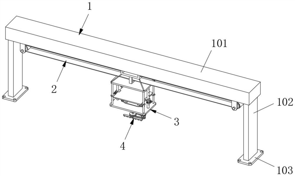
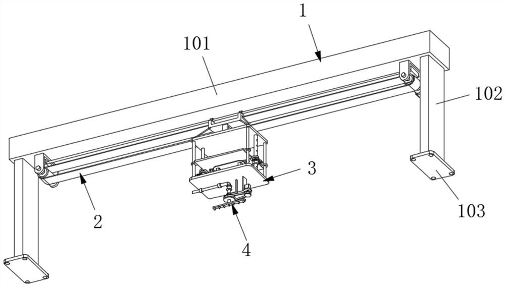
[0066] Such as Figure 1-10 As shown, a steel-concrete composite beam cantilever roof pouring adjustable cast-in-place support platform according to an embodiment of the present invention includes a support mechanism 1, a drive mechanism 2 installed on the support mechanism 1, and a drive mechanism 2 installed on the drive mechanism 2. The hanging mechanism 3 on the top and the spray mechanism 4 installed on the hanging mechanism 3;

[0067] Wherein, the supporting mechanism 1 includes a Bailey cantilever beam 101, both sides of the bottom of the Bailey cantilever beam 101 are fixedly connected with a support section steel 102, and the bottom of the support section steel 102 is fixedly connected with a support base 103;

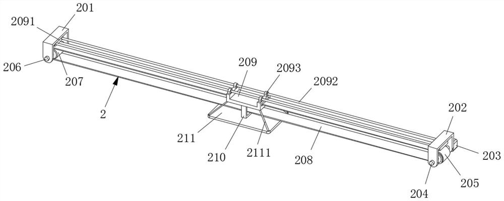
[0068] Wherein, the driving mechanism 2 includes a first driving frame 201 and a second driving frame 202 symmetrically connected to both sides of the bottom of the Bailey beam 101, and the side of the second driving frame 202 is fixedly connected with a serv...

Embodiment 2

[0082] Such as Figure 1-10 As shown, the difference between this embodiment and Embodiment 1 is that the tops of the inner walls of the first driving frame 201 and the second driving frame 202 are fixedly connected with mounting blocks 2091, and the two mounting blocks 2091 are fixed between Two guiding slides 2092 are connected, and symmetrically arranged guide sliding sleeves 2093 are slidably connected to the guiding slides 2092, and the bottom of the guide sliding sleeves 2093 is fixedly connected with the top of the installation frame 209, and the top plate The four corners of the top of 211 are fixedly connected with reinforcing ribs 2111 , and the other end of the reinforcing ribs 2111 is fixedly connected with the corners of the bottom of the installation frame 209 .

[0083] By adopting the above technical solution, the installation frame 209 can be limited, thereby increasing the sliding stability of the installation frame 209 and increasing the installation stabili...

Embodiment 3

[0085] Such as Figure 1-10 As shown, the difference between this embodiment and Embodiment 2 is that the bottom mounting ear 3022 is fixedly mounted on the top of the bottom plate 3012 through mounting screws, and the top mounting ear 3025 is fixedly mounted on the construction surface through mounting screws. The bottom of platform 3014.

[0086]By adopting the above technical solution, it is convenient to disassemble and install the jack 3023, thereby facilitating the maintenance of the jack 3023.


PUM


Abstract

The invention discloses an adjustable cast-in-place support platform for pouring of a steel-concrete composite beam cantilever top plate. The adjustable cast-in-place support platform comprises a supporting mechanism, a driving mechanism installed on the supporting mechanism, a hanging mechanism installed on the driving mechanism and a spraying mechanism installed on the hanging mechanism. The supporting mechanism comprises a bailey cantilever beam. According to the method, the hoisted steel box girder serves as an acting point, and the supporting mechanism is installed on the steel box girder panel to bear all loads of the cantilever section; a safety channel is established under the mutual cooperation effect of the driving mechanism and the hanging mechanism, the operation safety of operators is guaranteed, and the elevation and the linetype of the hanging assembly are conveniently and flexibly adjusted through the lifting assembly. The spraying mechanism is used for conveniently spraying and curing the concrete of the cantilever section; therefore, a convenient, safe, fast and low-cost construction platform is created for construction of the steel-concrete composite beam cantilever top plate, and the construction platform is particularly suitable for pouring construction of the steel-concrete composite beam cantilever top plate at high altitude and across roads.

Description

technical field [0001] The invention relates to the technical field of construction of a steel-concrete composite beam cantilever roof, in particular to an adjustable cast-in-place support platform for pouring a steel-concrete composite beam cantilever roof. Background technique [0002] With the rapid development of steel structure technology in my country, steel-concrete composite bridges are widely used in new roads at this stage. Bridges with this type of structure have a series of advantages such as high rigidity, short construction period, high load-bearing performance, and good appearance quality, so they have been widely used at this stage. [0003] Steel box girder bridge decks often use C50 composite fiber concrete, and the concrete is a cantilever structure with a cantilever length of 1.5m-2.0m. This is a traditional construction method for complex environments such as bridges with limited clear heights and bridges spanning railways, rivers, and highways. The con...

Claims


Application Information

Patent Timeline
Patent Type & Authority Applications(China)
IPC IPC(8): E01D21/00E01D19/00B05B15/68E01D101/26
CPCE01D21/00E01D19/00B05B15/68E01D2101/268
Inventor 王国友赖炳增卢国庆王海丽王金山隋国瑞方鑫伟
Owner CCCC FIRST HIGHWAY XIAMEN ENG
Learn More