
Textile fabric dyeing equipment for spinning

A technology for dyeing equipment and textiles, which is applied in the processing of textile materials, equipment configuration, textiles and papermaking, and textile materials processing. It can solve the problems of affecting dyeing efficiency, lack of reach, and low convenience, and improve work efficiency. , increase the probability of contact, and improve the effect of convenience

Inactive Publication Date: 2022-05-10
牛荣辉
View PDF0 Cites 0 Cited by
  • Summary
  • Abstract
  • Description
  • Claims
  • Application Information

AI Technical Summary

Problems solved by technology

[0003] The lower part of the inner cavity of the dyeing equipment is provided with a roller, which is used to support and turn the textile immersed in the dyeing pool. Before dyeing, the front end of the textile needs to pass through the roller inside the dyeing pool. This step is generally done manually. The convenience is not high. In addition, the existing dyeing equipment directly soaks the textile fabric in the dyeing pool. The efficiency of the contact between the dye and the textile fabric is not high, which affects the dyeing efficiency and cannot meet the requirements of today’s use. Therefore, we proposed A kind of textile dyeing equipment for textile

Method used

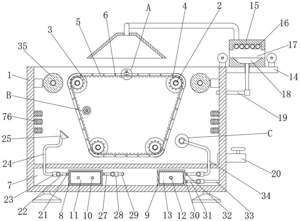
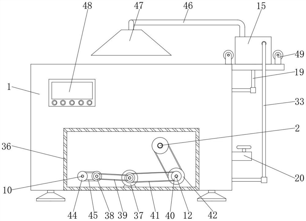
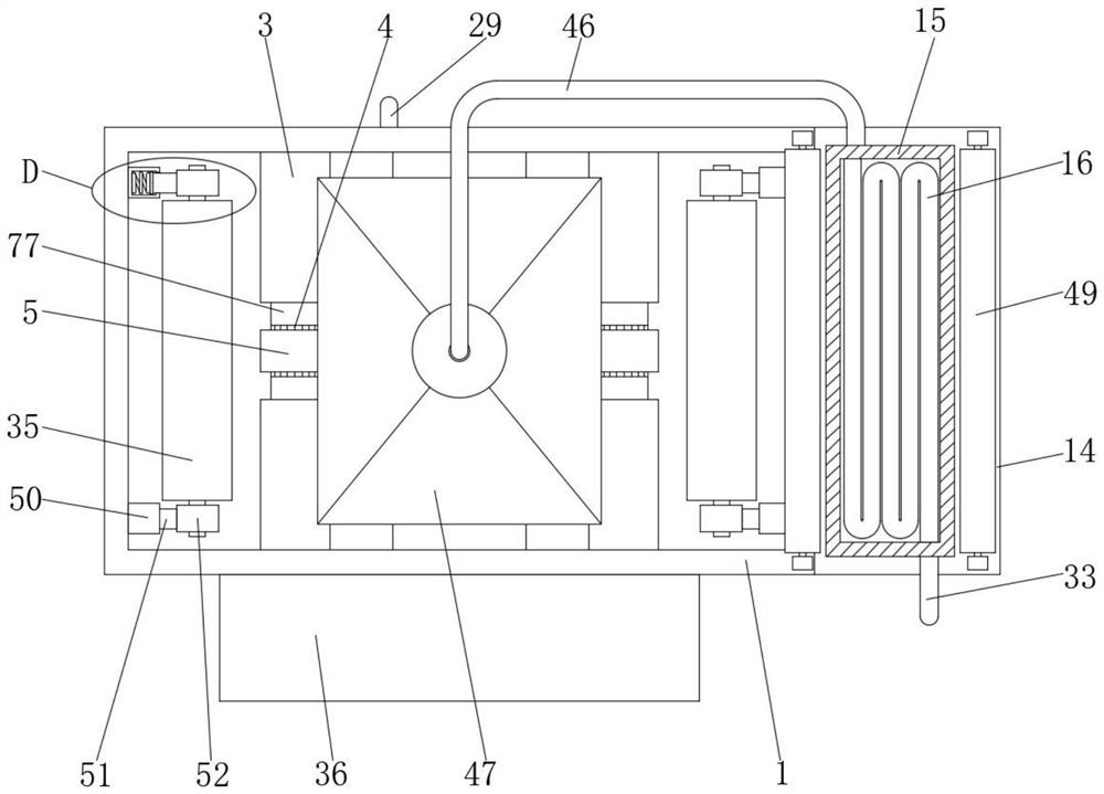

Image

  • Textile fabric dyeing equipment for spinning
  • Textile fabric dyeing equipment for spinning
  • Textile fabric dyeing equipment for spinning

Examples


Embodiment Construction

[0029] The following will clearly and completely describe the technical solutions in the embodiments of the present invention with reference to the accompanying drawings in the embodiments of the present invention. Obviously, the described embodiments are only some, not all, embodiments of the present invention.

[0030] see Figure 1 to Figure 11 , the present invention provides a technical solution: a kind of textile dyeing equipment for weaving, comprising a dyeing box 1, a gear belt 5, a first transmission belt 39, a second transmission belt 41, a third transmission belt 43, a fourth transmission belt 45, and a dyeing box 1 There are four rotating shafts 2 connected in rotation in the inner cavity of the four rotating shafts 2, and the driving rollers 3 are fixedly sleeved on the surfaces of the four rotating shafts 2. The middle parts of the four driving rollers 3 are respectively provided with avoidance grooves 77, and the middle parts of the four avoidance grooves 77 are...


PUM


Abstract

The invention discloses textile fabric dyeing equipment for spinning, and relates to the technical field of textile equipment, the textile fabric dyeing equipment comprises a dyeing box, a gear belt, a first transmission belt, a second transmission belt, a third transmission belt and a fourth transmission belt, an inner cavity of the dyeing box is rotatably connected with four rotating shafts, and the surfaces of the four rotating shafts are fixedly sleeved with driving rollers. According to the textile fabric dyeing equipment for spinning, before dyeing, a clamping plate and a clamping plate are installed on a gear belt, the front end of a to-be-dyed textile fabric is placed into an inner cavity of a clamping groove, the textile fabric located in the inner cavity of the clamping groove is clamped through an extrusion block, and a servo motor is started to drive a roller and the gear belt to rotate anticlockwise; and then the clamping plates drive the textile fabric to rotate anticlockwise, so that the front end of the textile fabric smoothly penetrates through the driving roller at the bottom of the inner cavity of the dyeing box and moves to the upper portion of the other end of the inner cavity of the dyeing box, the function of penetrating the textile fabric into the dyeing equipment is achieved, and the convenience of the textile fabric dyeing equipment for spinning is improved.

Description

technical field [0001] The invention relates to the technical field of textile equipment, in particular to textile dyeing equipment for textile use. Background technique [0002] Textile fabrics are flat and soft pieces formed by intersecting, knotting, and connecting small and long objects. Woven fabrics are composed of yarns with intersecting relationships. Knitted fabrics are composed of yarns with intersecting relationships. Textiles are composed of yarns that are connected, and the third fabric is composed of yarns that are intersected and knotted. In the process of fabric manufacturing, it needs to be dyed with different colors after weaving. The process requires the use of dyeing equipment. [0003] The lower part of the inner cavity of the dyeing equipment is provided with a roller, which is used to support and turn the textile immersed in the dyeing pool. Before dyeing, the front end of the textile needs to pass through the roller inside the dyeing pool. This step ...

Claims


Application Information

Patent Timeline
IPC IPC(8): D06B3/10D06B3/20D06B23/20D06B23/04
CPCD06B3/10D06B3/20D06B23/20D06B23/04
Inventor 牛荣辉
Owner 牛荣辉
Learn More