Mouth frame assembly and transparent drawer box manufacturing method

A manufacturing method and technology of drawer boxes, which are applied in the directions of manufacturing tools, workpiece clamping devices, maintenance and safety accessories, etc., can solve the problems of manual manual support and low efficiency, and achieve the effect of easy storage and increased bearing capacity.

Pending Publication Date: 2022-05-10
扬州容维塑业有限公司
View PDF0 Cites 0 Cited by
  • Summary
  • Abstract
  • Description
  • Claims
  • Application Information

AI Technical Summary

Problems solved by technology

[0004] The purpose of the present invention is to pull the sliding block through the expansion and contraction of the cylinder, and set a splint on the sliding block, so as to clamp and fix the mouth frame assembly and the transparent drawer box, and then use the manufacturing method to It is processed to solve the problem that the existing manufacturing methods are mostly manually supported, and then the mouth frame components and transparent drawer boxes are processed through the processing facilities, which is not only inefficient, but also dangerous.

Method used


Image

  • Mouth frame assembly and transparent drawer box manufacturing method
  • Mouth frame assembly and transparent drawer box manufacturing method
  • Mouth frame assembly and transparent drawer box manufacturing method

Examples


Embodiment 1

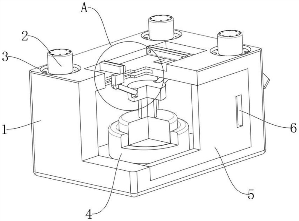
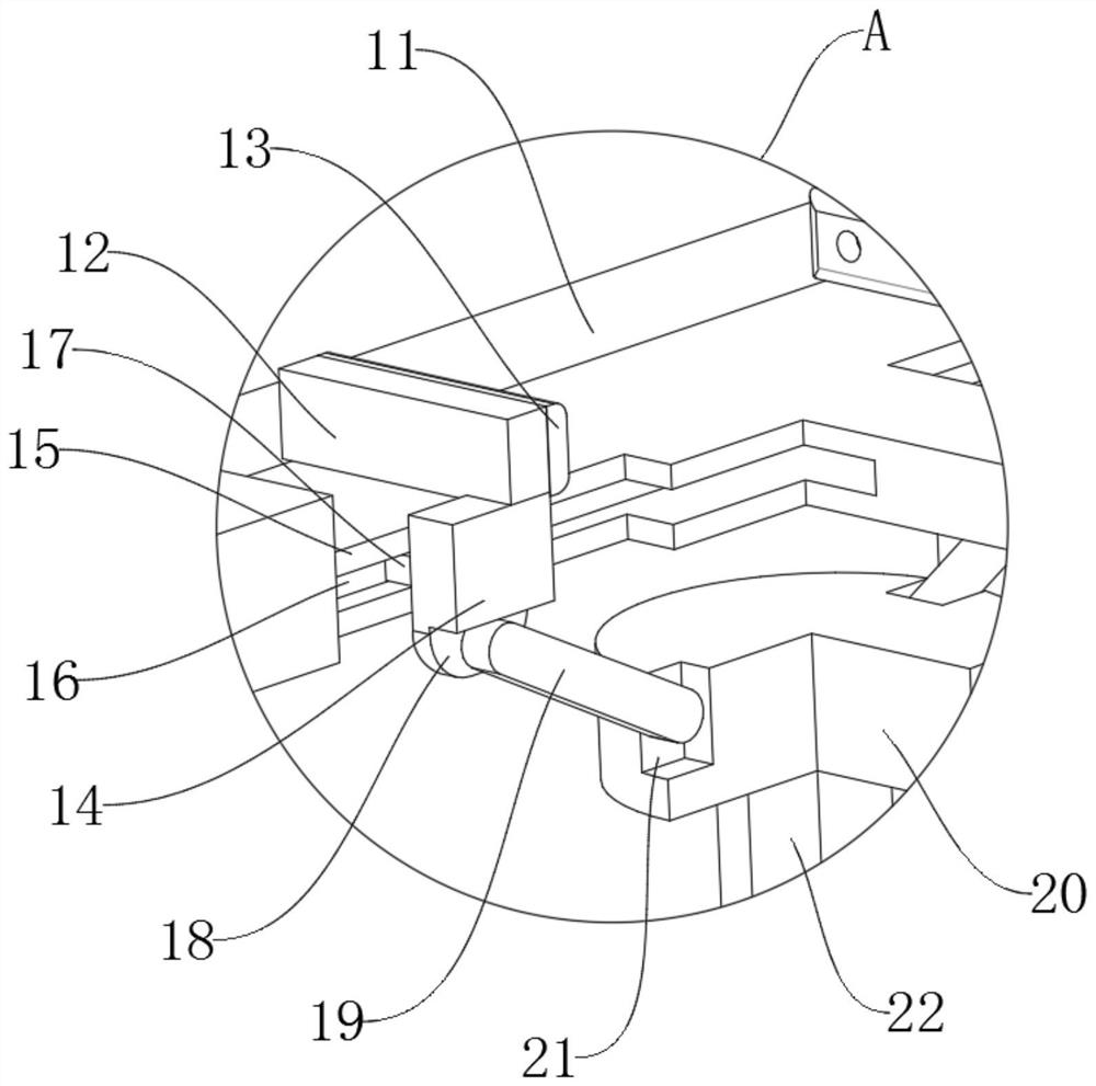
[0021] Example 1, such as Figure 1-3 As shown, the present invention provides a technical solution for the manufacturing method of the mouth frame assembly and the transparent drawer box: including the device body 1, the top of the device body 1 is provided with a limiting groove 11, and the inner bottom surface of the limiting groove 11 is provided near the edges of both sides. There are sliding grooves 15, the inner bottom surface of the device body 1 is fixed with a fixed sleeve 4, the inside of the fixed sleeve 4 is fixed with a cylinder 22, and the top of the cylinder 22 is fixed with a connecting plate 20, and the inner walls of both sides of the two sliding grooves 15 are opened. There are chute 16, and the inside of four chute 16 is slidingly connected with slider 17, and the four sliders 17 are divided into two groups, and the two sliders 17 located in each sliding groove 15 are a group, and each group A sliding block 14 is fixed between opposite sides of the two sli...

Embodiment 2

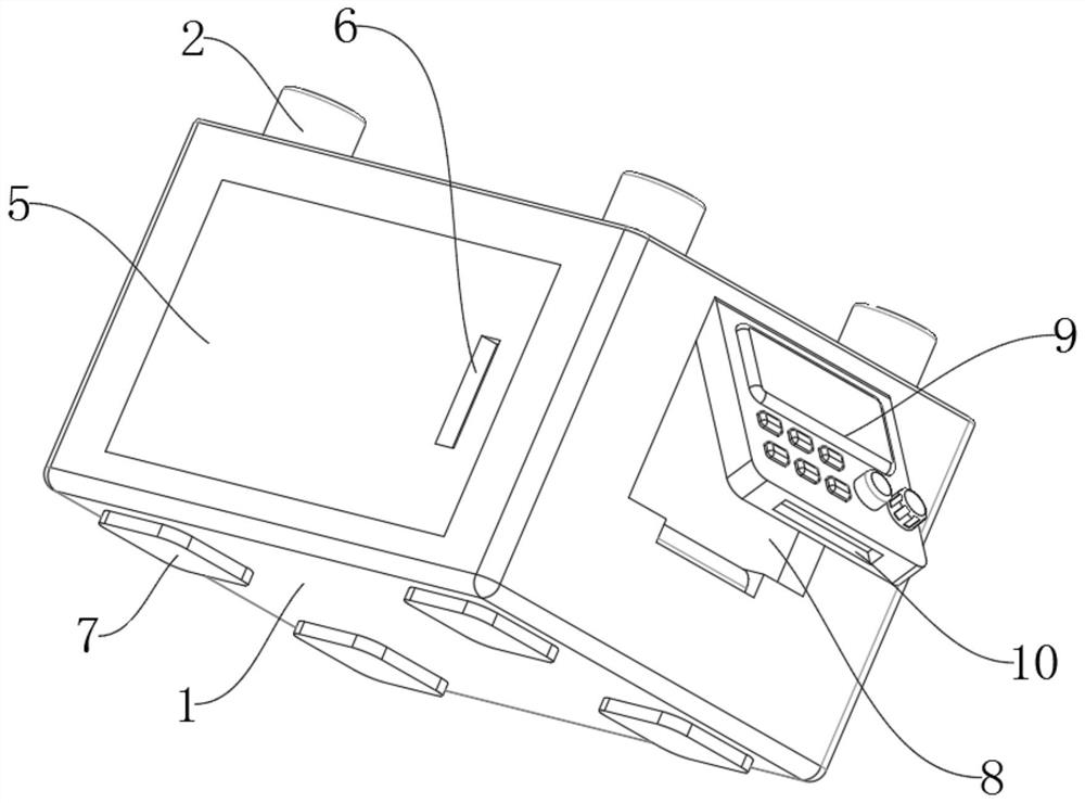
[0023] Example 2, such as Figure 1-3 As shown, the bottoms of the two sliding blocks 14 are provided with movable grooves 18, and the top of the connection plate 20 is provided with movable openings 21 near both sides, and the insides of the two movable grooves 18 are connected with connecting rods 19 through rotating shafts. One end of the two connecting rods 19 is connected to the inside of the movable port 21 through the rotation of the rotating shaft, the splint 12 is fixed on the top of the two sliding blocks 14, and the rubber pad 13 is fixed on one side of the two splints 12, and the device body 1 The front side of the front side near the side edge is connected with a safety cover 5 by hinge rotation, the front side of the safety cover 5 is provided with a groove 6 near the side edge, and the top of the device body 1 is provided with four fixing grooves 3, four The interior of each fixing groove 3 is fixed with a robot base 2, and the bottom of the device body 1 is fix...


PUM


Abstract

The invention provides an opening frame assembly and a transparent drawer box manufacturing method, and relates to the technical field of industrial automation. A machining device comprises a device body, a limiting groove is formed in the top of the device body, and sliding grooves are formed in the positions, close to the edges of the two sides, of the inner bottom face of the limiting groove; a fixing sleeve is fixed to the bottom face of the interior of the device body, an air cylinder is fixed to the interior of the fixing sleeve, a connecting disc is fixed to the top of the air cylinder, and sliding grooves are formed in the inner walls of the two sides of the two sliding grooves. The opening frame assembly and the transparent drawer box are clamped and fixed and then machined through a manufacturing method, and the problems that according to an existing manufacturing method, manual supporting is mostly adopted, then the opening frame assembly and the transparent drawer box are machined through machining facilities, efficiency is low, and danger exists are solved.

Description

technical field [0001] The invention relates to the technical field of industrial automation, in particular to a method for manufacturing a mouth frame assembly and a transparent drawer box. Background technique [0002] Industrial automation is the trend of widely using automatic control and automatic adjustment devices in industrial production to replace manual manipulation of machines and machine systems for processing and production. Under the conditions of industrial production automation, people only indirectly take care of and supervise the production of machines. Industrial automation can be divided into semi-automation according to its development stage. That is, some parts are produced by automatic control and automatic devices, while the other part is produced by manually operated machines. Fully automated. Refers to all the processes in the production process, including loading, unloading, loading and unloading, etc., do not require people to directly perform ...

Claims


Application Information

Patent Timeline
IPC IPC(8): B23Q3/08B23Q11/00B25B11/00
CPCB23Q3/08B23Q11/00B25B11/00
Inventor 胡爱丽张俊斌郭超
Owner 扬州容维塑业有限公司
Why Eureka
Try Eureka