
Additive and subtractive composite manufacturing equipment and using method thereof

A technology for manufacturing equipment, adding and subtracting materials, applied to other manufacturing equipment/tools, manufacturing tools, additive processing, etc., can solve problems such as large volume, difficult-to-process areas, and inability to process, so as to avoid large volume and expand applications Range, the effect of improving the processing quality

Active Publication Date: 2022-05-10
SHANTOU UNIV
View PDF13 Cites 1 Cited by
  • Summary
  • Abstract
  • Description
  • Claims
  • Application Information

AI Technical Summary

Problems solved by technology

[0002] The main failure modes of gears include broken teeth, fatigue pitting, tooth surface wear and tooth surface peeling, etc. The existing repair equipment for adding and subtracting materials mainly repairs the outer tooth surfaces of simple and large gears. However, when the gear has a complex structure, or When the repair area is a narrow position such as the tooth surface or tooth root of the gear, due to the complex structure and large volume of the existing equipment for adding and subtracting materials, the laser head, the processing device and the gear to be repaired are prone to interference and collision, making it difficult The processing area cannot guarantee the processing quality, or even processing

Method used


Image

  • Additive and subtractive composite manufacturing equipment and using method thereof
  • Additive and subtractive composite manufacturing equipment and using method thereof
  • Additive and subtractive composite manufacturing equipment and using method thereof

Examples


Embodiment Construction

[0023]The idea, specific structure and technical effects of the present invention will be clearly and completely described below in conjunction with the embodiments and accompanying drawings, so as to fully understand the purpose, features and effects of the present invention. Apparently, the described embodiments are only some of the embodiments of the present invention, rather than all of them. Based on the embodiments of the present invention, other embodiments obtained by those skilled in the art without creative efforts belong to The protection scope of the present invention. In addition, all connection relationships mentioned in this article do not refer to the direct connection of components, but mean that a better connection structure can be formed by adding or reducing connection accessories according to specific implementation conditions. The various technical features in the present invention can be combined interactively on the premise of not conflicting with each ...


PUM


Abstract

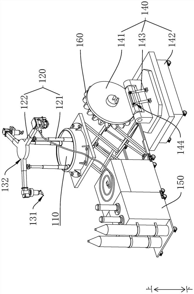
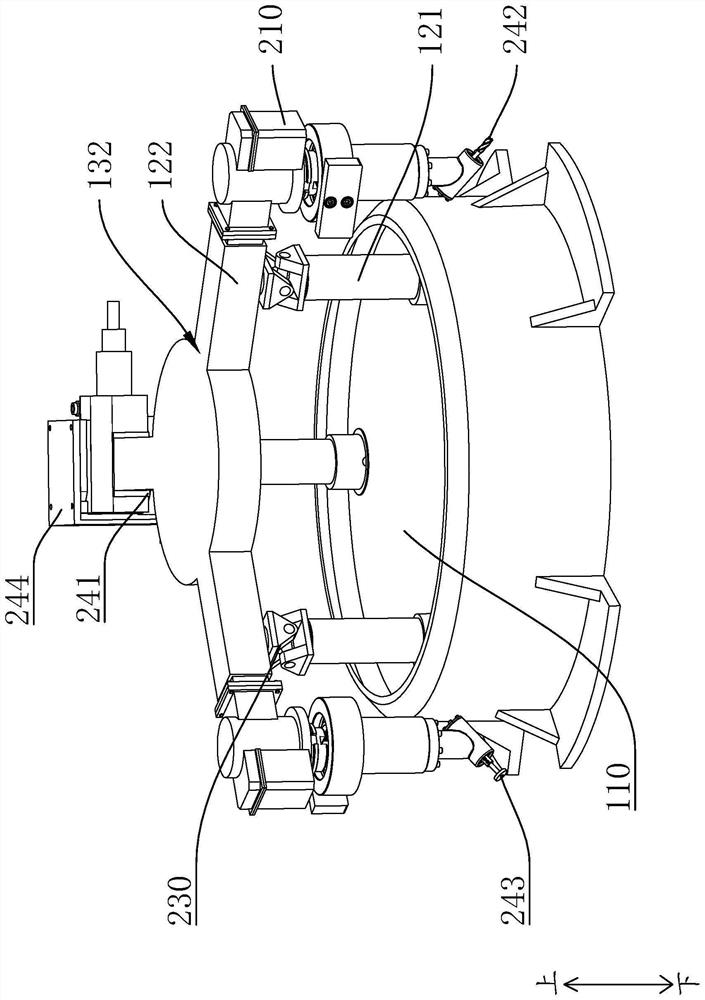
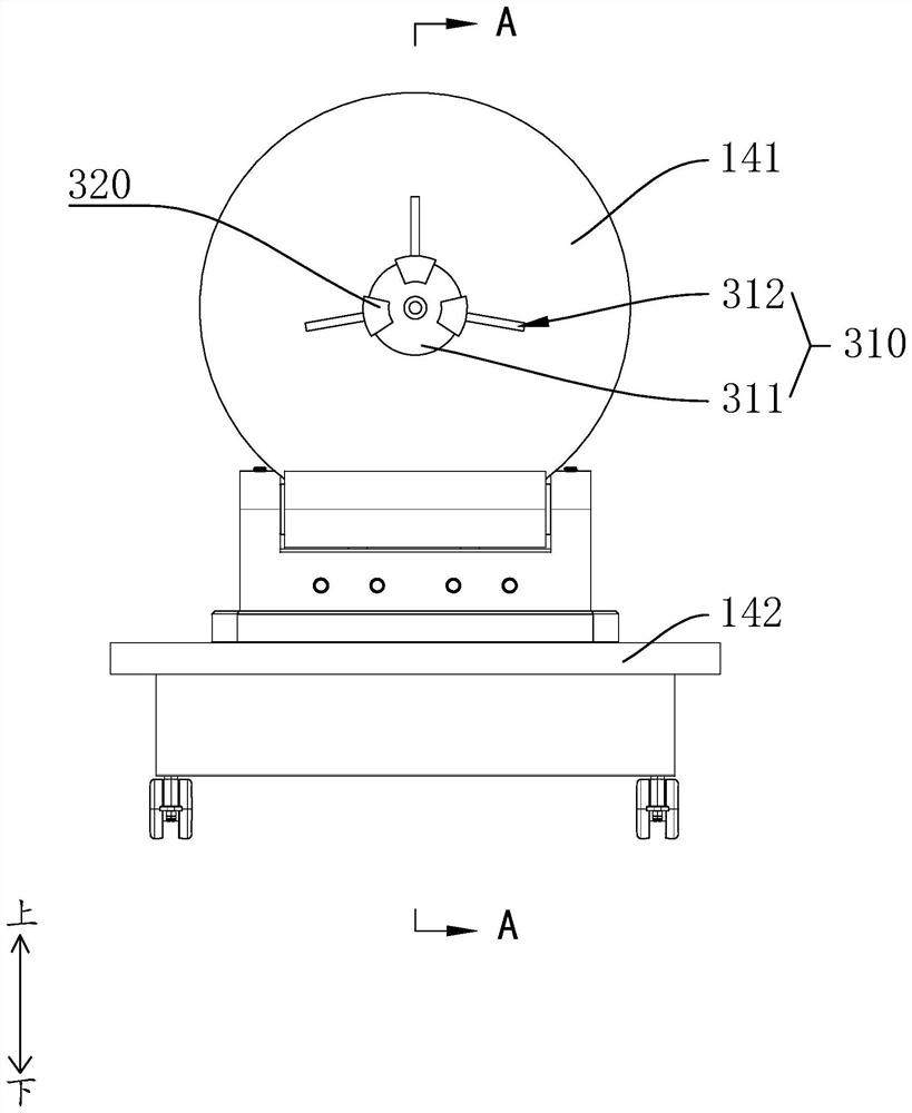
The additive and subtractive composite manufacturing equipment comprises a rotating disc, and the rotating axis of the rotating disc is parallel to the central axis of the rotating disc; the height adjusting part is provided with a fixed end and a movable end, the fixed end is arranged on the rotating disc, and the movable end moves on the fixed end in the vertical direction; the machining units are arranged at the movable ends, each machining unit comprises a connecting frame, one end of each connecting frame is provided with a telescopic machining end, the other end of each connecting frame serves as a convergence end, the two or more machining units are arranged at intervals in the circumferential direction of the rotating axis of the rotating disc, and the convergence ends are connected in a positioning mode, so that switching of the machining ends can be achieved; the other ends of the multiple connecting frames extend outwards in a diverging mode with the converging end as the center, the distance between every two adjacent machining ends can be increased, interference is reduced, collision between the machining device and a failure gear or even other equipment is reduced, the occupied size of the equipment is reduced, a workpiece in a narrow repairing area can be machined conveniently, and the machining precision is improved.

Description

technical field [0001] The invention relates to the field of additive and subtractive material composite manufacturing, in particular to an additive and subtractive material composite manufacturing equipment and a use method thereof. Background technique [0002] The main failure modes of gears include broken teeth, fatigue pitting, tooth surface wear and tooth surface peeling, etc. The existing repair equipment for adding and subtracting materials mainly repairs the outer tooth surfaces of simple and large gears. However, when the gear has a complex structure, or When the repair area is a narrow position such as the tooth surface or tooth root of the gear, due to the complex structure and large volume of the existing equipment for adding and subtracting materials, the laser head, the processing device and the gear to be repaired are prone to interference and collision, making it difficult The processing area cannot guarantee the processing quality, or even processing. Con...

Claims


Application Information

Patent Timeline
Patent Type & Authority Applications(China)
IPC IPC(8): B23P23/00B23Q3/00B33Y30/00
CPCB23P23/00B23Q3/00B33Y30/00B23Q2703/10Y02P10/25
Inventor 王奉涛潘嘉欣来佑彬
Owner SHANTOU UNIV
Learn More