


Quick Research
Generate reliable direction feasibility study reports for your R&D in just a few steps.

Technical Q&A
Discover and master advanced knowledge NOW. Basics, ideas, possibilities, all at once.

Find Solutions
As an expert in R&D theories, this can generate solutions to your technical problems instantly.

Evaluate Feasibility
Analyze your overall solution with one click, know your potential R&D risks in advance.

Monitor Landscape
Get weekly tech updates, stay abreast of the latest tech innovations and key insights.
Metal pipeline butt-welding type welding device for metallurgy
A technology for welding devices and metal pipes, applied in welding equipment, metal processing equipment, resistance welding equipment, etc., can solve the problems of no protection, affecting work efficiency, and potential safety hazards, and achieves increased stability, automatic lifting of pipes, The effect of improving work efficiency
- Summary
- Abstract
- Description
- Claims
- Application Information
AI Technical Summary
Problems solved by technology
Method used
Image

Examples
Embodiment 1
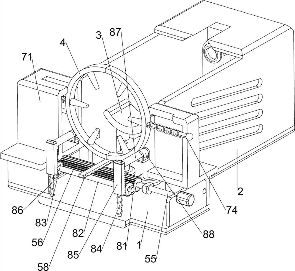
[0031] A butt-welding welding device for metal pipes for metallurgy, such as Figure 1-Figure 7 As shown, it includes a bottom plate 1, a casing 2, a placement frame 3, a welding device 4, a clamping mechanism 5, a rotating mechanism 6, and a welding mechanism 7. The frame 3 and the placement frame 3 are both located inside the shell 2, a welding mechanism 7 is provided between the bottom plate 1 and the middle of the shell 2, two welding devices 4 are provided on the welding mechanism 7, and a clamping mechanism 5 is provided on the top of the bottom plate 1. Tight mechanism 5 is provided with rotating mechanism 6.
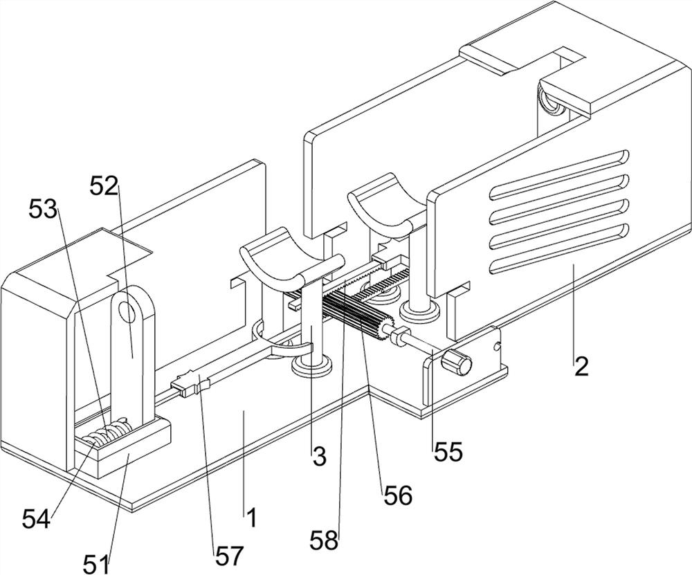
[0032] The clamping mechanism 5 includes a fixed block 51, a slide plate 52, a first guide rod 53, a first spring 54, a first rotating shaft 55, a gear column 56, a guide rail 57 and a long rack 58, and the left and right sides of the bottom plate 1 are provided with fixed Block 51, fixed block 51 inner sides are all provided with first guide bar 53, all sliding...
Embodiment 2
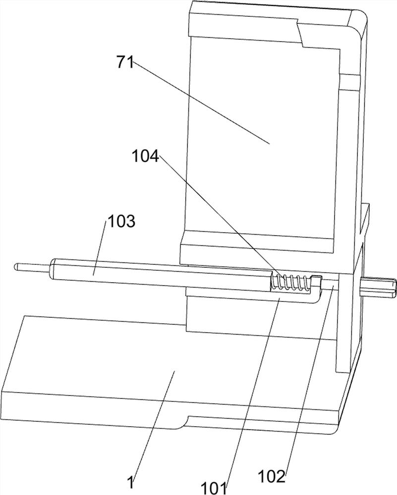
[0037] On the basis of Example 1, such as Figure 8-Figure 11 As shown, a push assembly 8 is also included, and the push assembly 8 includes a swivel base 81, a third rotating shaft 82, a full gear 83, a third guide rod 84, a short rack 85, a third spring 86, an engaging rod 87 and a roller 88 , the inner left side of the support frame 71 is provided with a swivel seat 81, and the inner side of the swivel seat 81 is rotatably provided with a third rotating shaft 82. The front and rear sides of the third rotating shaft 82 are provided with full gears 83. Engagement, bottom plate 1 top front and rear sides are provided with the 3rd guide rod 84, and the 3rd guide rod 84 is all positioned at the left side of the 3rd rotating shaft 82, and all sliding type is provided with short rack 85 on the 3rd guide rod 84, and short rack 85 All are meshed with the full gear 83, and the third spring 86 is arranged between the short rack 85 and the base plate 1, and the third spring 86 is set o...
PUM
 Abstract
Description
Claims
Application Information
 - R&D Engineer
- R&D Manager
- IP Professional
- Industry Leading Data Capabilities
- Powerful AI technology
- Patent DNA Extraction
Browse by: Latest US Patents, China's latest patents, Technical Efficacy Thesaurus, Application Domain, Technology Topic, Popular Technical Reports.
© 2024 PatSnap. All rights reserved.Legal|Privacy policy|Modern Slavery Act Transparency Statement|Sitemap|About US| Contact US: help@patsnap.com