
High-voltage high-capacity power electronic switching station device

A technology of power electronics and switching switches, applied in electronic switches, electrical components, cooling/ventilation/heating transformation, etc., can solve the application requirements of high-voltage and large-capacity open-winding motor drive systems, and is not suitable for open-winding motor drive systems. Occasion, short service life and other problems, to achieve the effect of compact structure, improved adaptability and long service life

Pending Publication Date: 2022-05-06
NAVAL UNIV OF ENG PLA
View PDF0 Cites 0 Cited by
  • Summary
  • Abstract
  • Description
  • Claims
  • Application Information

AI Technical Summary

Problems solved by technology

The mechanical switch has high working voltage and high current, but has the disadvantages of slow response in the switching process, intermittent and large fluctuations in current, short service life, and large volume. It is not suitable for open-winding motor drive systems with high dynamic response under high voltage and large capacity. Applications
During the working process of the electronic switch, the switching response is fast, the current is continuous, and there are no mechanical parts, so the service life is long. Large, unable to meet the application requirements of high-voltage and large-capacity open-winding motor drive systems

Method used


Image

  • High-voltage high-capacity power electronic switching station device
  • High-voltage high-capacity power electronic switching station device
  • High-voltage high-capacity power electronic switching station device

Examples


Embodiment Construction

[0026] The present invention will be further described in detail below in conjunction with the accompanying drawings and specific embodiments. Apparently, the described embodiments are only some of the embodiments of the present invention, not all of them. Based on the embodiments of the present invention, all other embodiments obtained by persons of ordinary skill in the art without making creative efforts belong to the protection scope of the present invention.

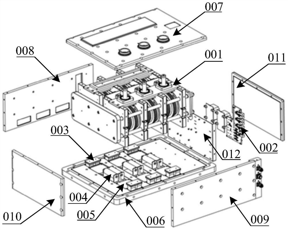
[0027] Such as Figure 2~3 The shown high-voltage large-capacity power electronic switching station device includes a metal shell surrounded by a base plate 006, a top plate 007, a rear cover plate 008, a front plate 009, a left plate 010, and a right plate 011, and a built-in metal shell Press-fit the module unit 001 and the control unit 002 of the power device.

[0028]The control unit 002 includes a power supply module and a control signal processing board, both of which are installed on the control circuit fixi...


PUM


Abstract

The invention discloses a high-voltage high-capacity power electronic switching station device which comprises a metal shell and a power device press-fitting module unit arranged in the metal shell. Each power device press-fitting module unit comprises an upper bidirectional switch valve string and a lower bidirectional switch valve string which are connected in series through a short-circuit copper bar, and the requirements for high-voltage and large-capacity output are met. A voltage-sharing resistor RA3 in the A-phase upper bidirectional switch and a voltage-sharing resistor RA4 in the A-phase lower bidirectional switch are arranged between the A-phase upper bidirectional switch and the A-phase lower bidirectional switch, so that the two voltage-sharing resistors which are connected in series bear the same voltage stress in a static state; a voltage-sharing resistance insulating plate is arranged between the upper bidirectional switch valve string and the lower bidirectional switch valve string so as to enhance the electrical insulation performance between the two.

Description

technical field [0001] The invention belongs to the technical field of high-power electric power electronics, and in particular relates to a high-voltage large-capacity power electronic switch station device. Background technique [0002] The open-winding motor is to open the neutral point of the traditional motor winding, and two sets of frequency converters are respectively connected to both ends of the stator winding to realize the series connection of the frequency converters, which can obtain greater system output power and more levels of power supply effects, and Meet the needs of high-power applications. With the development of open-winding motor system technology gradually matures, the advantages and potential of its topology structure with high redundancy and fault tolerance are constantly being tapped, and its application research in different fields is receiving more and more attention from academia and industry at home and abroad. s concern. For the open-windin...

Claims


Application Information

Patent Timeline
IPC IPC(8): H03K17/725H03K17/735H05K7/20
CPCH03K17/735H03K17/725H05K7/2039H03K2217/0009
Inventor 李卫超周亮邓晨晏明钟颖韩金洋张向明李兵
Owner NAVAL UNIV OF ENG PLA
Learn More