Method for monitoring safe operation of catalytic oil-free compression system

A technology of compression system and safe operation, applied in chemical instruments and methods, separation methods, pump testing, etc., can solve the problems of lag in detection data, inability to effectively ensure user gas quality, and inability to provide early feedback

Pending Publication Date: 2022-05-06
NINGBO BAOSI ENERGY EQUIP
View PDF0 Cites 0 Cited by
  • Summary
  • Abstract
  • Description
  • Claims
  • Application Information

AI Technical Summary

Problems solved by technology

[0004] Although, installing oil content detection equipment at the exhaust end of the compressor can confirm whether the compressor is running out of oil, and installing oil content detection equipment at the exhaust end of the catalytic purification equipment can confirm whether the oil removal efficiency of the catalytic purification equipment is normal, However, the detection rate of the oil content detection equipment in the prior art is not as fast as the flow rate of high-pressure gas. Often, the detected compressed air has already entered the user's gas equipment before the detection results come out, so that the oil content detection equipment will The detection data lags behind, and the oil content cannot be fed back before the compressed air enters the user's gas equipment, and the quality of the gas used by the user cannot be effectively guaranteed.

Method used


Image

  • Method for monitoring safe operation of catalytic oil-free compression system
  • Method for monitoring safe operation of catalytic oil-free compression system

Examples


Embodiment 1

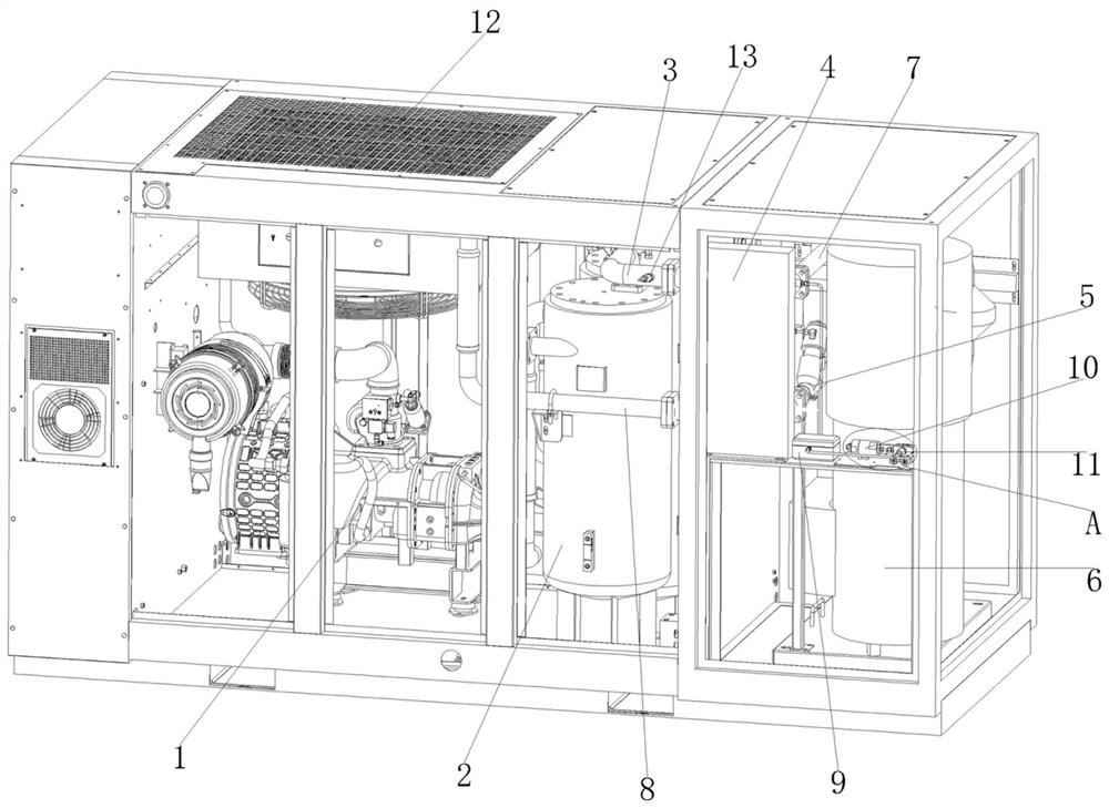
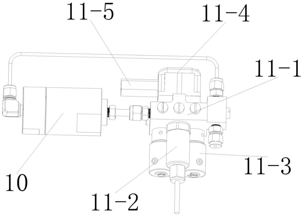
[0029] The method for monitoring the safe operation of the catalytic oil-free compression system of the present invention uses a catalytic oil-free compression system such as figure 1 As shown in , including compressor, oil-gas separator (not shown), gas-liquid separator 2, catalytic converter 6, heat exchanger, first oil content detection device 13, second oil content detection device 11, electronic cooling 9, filter adsorption tank 10, radiator 12, gas-liquid separation exhaust pipe 3, display screen (not shown) and alarm (not shown), the compressor adopts oil-injected screw compressor 1, and radiator 12 is installed Above the oil-injected screw compressor 1 , the oil-injected screw compressor 1 compresses air and is lubricated with lubricating oil during operation, and the radiator 12 radiates heat and cools down the oil-injected screw compressor 1 in time. The heat exchanger adopts a partition-type heat exchanger 4, and the partition-type heat exchanger 4 is provided with ...

Embodiment 2

[0040] The difference between the method for monitoring the safe operation of the catalytic oil-free compression system in this embodiment and that in Embodiment 1 is that in the catalytic oil-free compression system adopted in this embodiment, the catalytic intake pipe 5 is provided with a catalytic converter intake pipe and a pair of The air exhaust pipe, the catalytic converter intake pipe is connected and communicated with the air inlet of the catalytic converter, the catalytic converter intake pipe is used to introduce compressed gas into the catalytic converter, and the empty exhaust pipe is not connected with the air intake of the catalytic converter. The air discharge pipe is used to discharge the compressed gas to the air. Valves are arranged in both the intake pipe of the catalytic converter and the air discharge pipe. Open the valve of the catalytic air intake pipe to introduce the compressed gas into the catalytic converter, and close the valve to the empty exhaust ...

Embodiment 3

[0042] The difference between the method for monitoring the safe operation of the catalytic oil-free compression system in this embodiment and that in Embodiment 1 is that in the catalytic oil-free compression system used in this embodiment, the heat exchange exhaust pipe 8 is provided with an air supply pipe and a pair of The air exhaust pipe and the air supply pipe are used to connect and supply gas to the gas-consuming equipment, and the air-to-air exhaust pipe is used to discharge compressed gas to the air. Valves are arranged on the air-supply pipe and the air-to-air exhaust pipe. When the catalytic oil-free compression system is running normally and the oil content of the compressed gas does not exceed the standard, the valve of the gas supply pipe can be opened and the valve of the air exhaust pipe can be closed. The catalytic oil-free compression system of the present invention passes through the gas supply pipe Continuously supply gas to the user's gas equipment to ens...


PUM


Abstract

The invention provides a method for monitoring safe operation of a catalytic oil-free compression system, which comprises the following steps of: catalytically decomposing oil impurities in compressed gas by using a catalytic purifier, and respectively arranging first oil content detection equipment and second oil content detection equipment at the gas inlet end and the gas outlet end of the catalytic purifier to detect the oil content of the compressed gas, the oil content of the compressed gas purified by the catalytic purifier is firstly detected by the second oil content detection equipment, then the compressed gas is buffered and decelerated by the buffer equipment, and the buffer time of the compressed gas in the buffer equipment is longer than the detection time of the second oil content detection equipment; detection results of the first oil content detection equipment and the second oil content detection equipment and a difference value between the detection results are displayed on the display screen. According to the method, a user can master the working states of the compressor and the catalytic purifier in real time, whether the compressor leaks oil or not and whether a catalyst in the catalytic purifier faces the overload risk or not are judged, the gas quality of the user is guaranteed, and the safety of the whole machine is protected.

Description

technical field [0001] The invention relates to the technical field of compressed air purification, in particular to a method for monitoring the safe operation of a catalytic oil-free compression system. Background technique [0002] As a cheap power source, compressed air is widely used in various industries, such as equipment driving, material conveying, drying, blowing, purging, pneumatic instrument components, automatic control, etc. Compressors that prepare compressed air have high power and have high requirements for lubrication and heat dissipation during operation. Compared with oil-free compressors such as dry compressors or water-lubricated compressors, compressors that use lubricating oil can obtain better lubrication effects , higher heat dissipation efficiency and lower cost, but the compressed air produced will inevitably contain oil impurities. In special industries such as electronics, food, medicine, and textiles, since oily impurities can cause harm to pro...

Claims


Application Information

Patent Timeline
Patent Type & Authority Applications(China)
IPC IPC(8): F04B49/06F04B49/10B01D53/86
CPCF04B49/06F04B49/10B01D53/86F04B2205/50
Inventor 张超萍张炯焱王泉超
Owner NINGBO BAOSI ENERGY EQUIP
Why Eureka
Try Eureka