
Speed change device

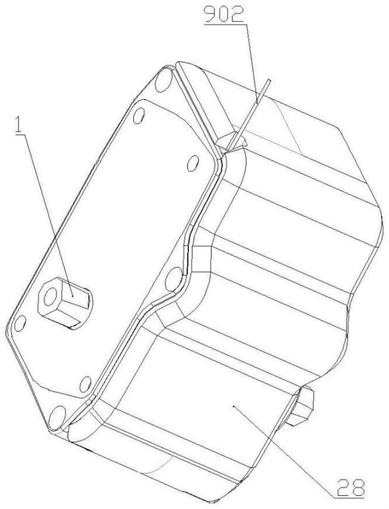
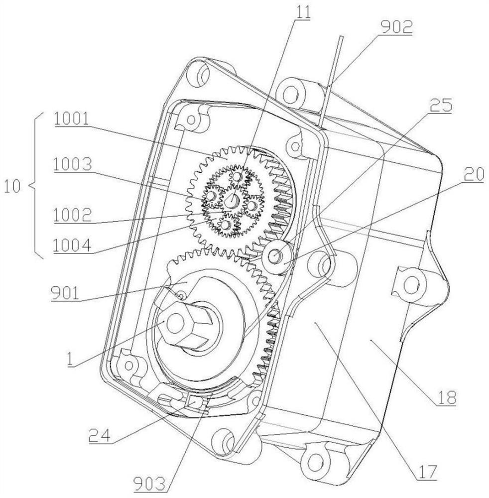
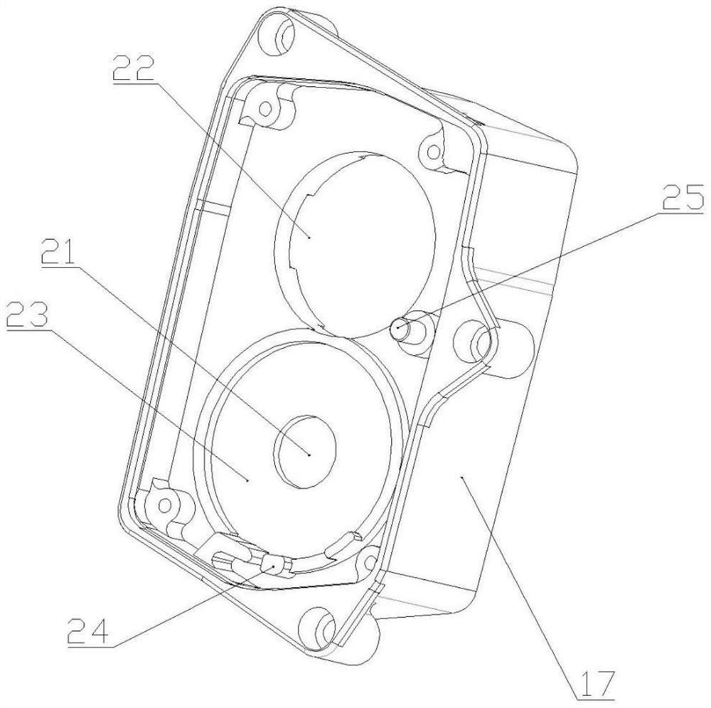
A speed change device and gear shifting technology, applied in the field of gearboxes, can solve the problems of low precision, complex structure and inflexibility, and achieve the effects of flexible shifting, simple structure and wide applicability

Pending Publication Date: 2022-04-29
朱红梅
View PDF2 Cites 0 Cited by
  • Summary
  • Abstract
  • Description
  • Claims
  • Application Information

AI Technical Summary

Problems solved by technology

[0003] When the speed change device is applied to a bicycle, in order to make the speed change function of the speed change bicycle richer, many improvements have been made to the speed change bicycle in the prior art, such as a patent with the publication number CN112026982A disclosing a new type of bicycle speed changer, which adopts a shaft sleeve combined The shifting method improves the performance of the transmission and can achieve six-speed shifting; however, the shifting device of this patent has poor flexibility and cannot realize shifting during driving, and the shifting process is not precise enough
Another example is that the patent with the publication number CN204533457U discloses a biaxial three-stage driven wheel gearbox device, which can normally shift gears with or without input speed; The small shrapnel exerts a restoring force on it, and the structure is more complicated
In addition, three holes are designed in the radial direction on the mandrel positioning block of this patent according to the proposed angle. Compression springs and steel balls are installed in the holes. Through the return positioning function of the steel balls, the gear shifting mandrel stops stably at an appropriate angle to realize shifting. gear, in the above gear shifting process, there are still problems of inflexibility and low precision in the return positioning of the steel ball

Method used


Image

  • Speed change device
  • Speed change device
  • Speed change device

Examples


Embodiment 1

[0060] In this embodiment, the device of the present invention can adjust nine gears, one gear is adjusted every 40° of rotation, and its specific structure is as follows:

[0061] Such as Figure 1-Figure 2 , Figure 5-Figure 7 , Figure 9-13 As shown in the figure, a speed change device includes a driving shaft 1 and a driven shaft 2, wherein the driving shaft 1 is provided with a driving wheel 3 and a third driven wheel 6, and the third driven wheel 6 is fixed on the driving shaft 1 through an output shaft Above, the output shaft is connected with the driving shaft 1 through a bearing; the driven shaft 2 is provided with a first driven wheel 4 matching with the driving wheel 3 and a second driven wheel 5 matching with the third driven wheel 6 ; The driven shaft 2 is also provided with a claw 8 that engages with the first driven wheel 4 and the second driven wheel 5 .

[0062] In the above structure, the number of the driving wheel 3, the first driven wheel 4, the second ...

Embodiment 2

[0084] In this embodiment, the device of the present invention can adjust six gears, one gear is adjusted every 60° of rotation, and its specific structure is as follows:

[0085] Such as Figure 1-Figure 2 , Figure 5-Figure 7 , Figure 9-13 As shown in the figure, a speed change device includes a driving shaft 1 and a driven shaft 2, wherein the driving shaft 1 is provided with a driving wheel 3 and a third driven wheel 6, and the third driven wheel 6 is fixed on the driving shaft 1 through an output shaft Above, the output shaft is connected with the driving shaft 1 through a bearing; the driven shaft 2 is provided with a first driven wheel 4 matching with the driving wheel 3 and a second driven wheel 5 matching with the third driven wheel 6 ; The driven shaft 2 is also provided with a claw 8 that engages with the first driven wheel 4 and the second driven wheel 5 .

[0086] In the above-mentioned structure, the quantity of driving wheel 3 and first driven wheel 4 is thr...

Embodiment 3

[0108] In this embodiment, the device of the present invention can adjust four gears, one gear is adjusted every 90° rotation, and its specific structure is as follows:

[0109] Such as Figure 1-Figure 2 , Figure 5-Figure 7 , Figure 9-13 As shown in the figure, a speed change device includes a driving shaft 1 and a driven shaft 2, wherein the driving shaft 1 is provided with a driving wheel 3 and a third driven wheel 6, and the third driven wheel 6 is fixed on the driving shaft 1 through an output shaft Above, the output shaft is connected with the driving shaft 1 through a bearing; the driven shaft 2 is provided with a first driven wheel 4 matching with the driving wheel 3 and a second driven wheel 5 matching with the third driven wheel 6 ; The driven shaft 2 is also provided with a claw 8 that engages with the first driven wheel 4 and the second driven wheel 5 .

[0110] In the above-mentioned structure, the quantity of driving wheel 3 and first driven wheel 4 is two; ...


PUM


Abstract

The invention belongs to the technical field of gearboxes, and discloses a speed changing device which comprises a driving shaft and a driven shaft, and the driving shaft is provided with a driving wheel and a third driven wheel; a first driven wheel matched with the driving wheel and a second driven wheel matched with the third driven wheel are arranged on the driven shaft; the driven shaft is further provided with a clamping jaw connected with the first driven wheel and the second driven wheel in a clamped mode. A clamping groove used for containing the clamping jaw is formed in the driven shaft, and a pressing piece spring is fixed to the clamping groove and connected with one end of the clamping jaw in an extruding mode. The gear shifting mechanism further comprises a gear shifting control assembly, a planet assembly and a gear shifting mandrel. Through cooperation of the first cam, the second cam and the clamping jaws, tilting and laying down of the clamping jaws at different clamping groove positions are controlled, the clamping jaws are further controlled to clamp the specific positions of the first driven wheel and the second driven wheel, and therefore output rotating speeds of multiple gears are generated under the condition that the input rotating speed is not changed.

Description

technical field [0001] The invention relates to the technical field of gearboxes, in particular to a speed change device. Background technique [0002] With the improvement of living standards, people's requirements for vehicles are no longer satisfied with traditional transportation functions, but also need to switch speeds flexibly in different scenarios; and speed, need to change the size of the wheel. The variable-speed vehicle can allow users to choose between low-speed gear and high-speed gear by switching the transmission, and adjust to low-speed gear when going uphill, and adjust to high-speed gear when going downhill, so as to achieve the purpose of saving effort on uphill and time-saving on downhill. [0003] When the speed change device is applied to a bicycle, in order to make the speed change function of the speed change bicycle richer, many improvements have been made to the speed change bicycle in the prior art, such as a patent with the publication number CN...

Claims


Application Information

Patent Timeline
IPC IPC(8): F16H3/089F16H57/00F16H57/021F16H53/08F16H59/04
CPCF16H3/089F16H57/0018F16H57/021F16H53/08F16H59/042F16H59/041F16H2200/0065F16H2200/0052F16H2200/0043F16H2003/0818
Inventor 朱红梅刘鸿图刘鸿铭
Owner 朱红梅
Learn More