Conduit oil outlet throttling structure and fuel oil prefilter shell assembly

An oil outlet and conduit technology, which is applied to the throttling structure of the conduit oil outlet and the fuel pre-filter housing assembly field, can solve the problem of reducing the service life of the filter element, reducing the pressure difference between the inside and outside of the exhaust hole, and affecting the fuel fluid. face and other issues to achieve the effect of ensuring utilization, smoothness, and smooth transition

Pending Publication Date: 2022-04-26
无锡亿利环保科技有限公司 +2
View PDF1 Cites 0 Cited by
  • Summary
  • Abstract
  • Description
  • Claims
  • Application Information

AI Technical Summary

Problems solved by technology

This exhaust structure has the following disadvantages: when the fuel flow rate of the fuel pre-filter is low, for example, when the fuel flow rate is 50L / min~250L / min, due to the low fuel flow rate, according to Bernoulli's theorem, the fluid flow rate and The static pressure of the fluid is inversely proportional. When the fluid flow rate decreases, the static pressure of the fluid will increase, that is, when the fuel flow rate is low, the static pressure will increase, and the pressure difference between the inside and outside of the exhaust hole will decrease, which is not conducive to the first The gas in the channel is exhausted, and the exhaust effect of the first channel is not good, which affects the rise of the fuel level, so that the fuel level cannot rise to a satisfactory height
[0004] The installation position of the fuel pre-filter is usually higher than the installation position of the automobile fuel tank. If there is leakage at the oil outlet pipe of the fuel pre-filter or the pipeline at the rear end of the oil outlet pipe due to seal failure, after the engine stops working, the external gas will It may enter the fuel outlet pipe from the leak, then pass through the electric pump, and enter the interior of the pre-filter from the pipe, causing too much gas to enter the interior of the pre-filter, resulting in a drop in the fuel level, thereby reducing the utilization rate of the filter element and reducing the use of the filter element time life

Method used


Image

  • Conduit oil outlet throttling structure and fuel oil prefilter shell assembly
  • Conduit oil outlet throttling structure and fuel oil prefilter shell assembly
  • Conduit oil outlet throttling structure and fuel oil prefilter shell assembly

Examples


no. 1 example

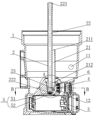
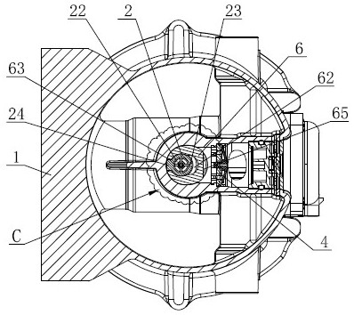
[0048] like figure 1 As shown, the housing 1 of the present invention is provided with an oil inlet pipe port 11 and an oil outlet pipe port 12, and the housing 1 is provided with a conduit 2, an electric pump 3 and a first one-way valve assembly 4; the conduit 2 is vertically inserted into the In the center of the casing 1 , the electric pump 3 is horizontally inserted under the conduit 2 , and the first check valve assembly 4 is arranged between the conduit 2 and the outlet pipe 12 , and can be unidirectionally opened toward the outlet 12 .

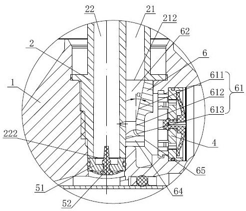
[0049] like figure 1 , figure 2 As shown, the conduit 2 is vertically provided with a fuel passage 21 and an air flow passage 22 through which the upper port of the fuel passage 21 is an oil inlet port 211, the lower port is an oil outlet port 212, and the upper port of the air flow passage 22 is an air intake port 221, The lower port is the air outlet port 222; the height of the oil inlet port 211 of the fuel passage 21 is shorter t...

no. 2 example

[0053] like Figure 7 As shown, different from the first embodiment, the throttling structure of this embodiment is directly integrally formed on the conduit 2 . On the conduit 2, located below the fuel passage 21, a throttle pipe portion 25 extends downward in the axial direction, which is the same as the block 6 of the first embodiment. Oil port 64, the first throttling passage 62 between the first throttling surface 61 and the outer wall surface of the air flow channel 22; 612 and the first arc surface section 613, which is small at the top and large at the bottom, respectively form an upper flow section with a flow cross-sectional area gradually decreasing from top to bottom in the first throttling passage 62, and the flow cross-sectional area is constant and relatively Narrow middle flow section, and lower flow section whose flow area gradually increases from top to bottom.

no. 3 example

[0055] like Figure 8 As shown, different from the first embodiment, the second one-way valve assembly 5 of this embodiment is directly integrated on the conduit 2 . The air outlet port 222 of the air flow channel 22 of the conduit 2 is integrally formed with a valve seat portion 26, and several air flow holes (not shown in the figure) are vertically opened on the valve seat portion 26. The valve of the second check valve assembly 5 The sheet 52 is inserted vertically on the valve seat portion 26 and can be opened in one direction downward toward the electric pump 3 .


PUM


Abstract

The invention discloses a guide pipe oil outlet throttling structure and a fuel oil prefilter shell assembly, a guide pipe is provided with a fuel oil channel and an airflow channel, the wall face of the airflow channel is provided with small exhaust holes, and the small exhaust holes are located below an oil outlet end opening of the fuel oil channel; a throttling channel is arranged below an oil outlet port of the fuel oil channel, located on the outer side of the small exhaust hole and communicated with the small exhaust hole, and the throttling channel comprises an upper overflowing section with the through-flow sectional area gradually reduced from top to bottom. An oil outlet is formed in the bottom of the throttling channel. The throttling structure is arranged below the fuel oil channel of the guide pipe, when fuel oil flows through the throttling structure, the flow speed of the fuel oil is increased, the static pressure of the fuel oil is reduced, the pressure difference between the two sides of the small exhaust holes is increased, and even if the flow speed of the fuel oil in the fuel oil channel is low, the fuel oil can be accelerated to the high flow speed level after flowing through the throttling structure; gas in the gas flow channel can be smoothly and continuously discharged, and it is guaranteed that the fuel oil liquid level can rise to the satisfactory height.

Description

technical field [0001] The invention relates to the technical field of fuel filters, in particular to a throttling structure of a conduit oil outlet and a housing assembly of a fuel prefilter. Background technique [0002] The fuel pre-filter is set in the engine fuel supply system, and is used to filter out impurities, water and other pollutants in the fuel, and then input it into the fuel delivery pump and fuel injector, so as to avoid excessive wear and tear of important parts such as fuel delivery pump and fuel injector. More or blockage and other problems to ensure the normal operation of the engine. The fuel pre-filter with electric pump is usually equipped with an exhaust structure, so that the gas at the upper end of the main housing can still be discharged through the oil outlet even after the electric pump stops working, so that the fuel liquid level of the fuel pre-filter rises to improve the filter element. utilization rate. [0003] The applicant's Chinese inv...

Claims


Application Information

Patent Timeline
Patent Type & Authority Applications(China)
IPC IPC(8): F02M37/54F02M37/32F02M37/48
CPCF02M37/54F02M37/32F02M37/48
Inventor 李星张金玲李骁祺覃文豪李权汤金鹏
Owner 无锡亿利环保科技有限公司
Why Eureka
Try Eureka