
Electric vehicle permanent magnet motor with stator and rotor integrated ventilation cooling structure

A ventilation cooling and electric vehicle technology, applied in electric vehicles, motors, electric components, etc., can solve the problem of safe and reliable operation of irreversible demagnetization of permanent magnets at the end of the motor, poor cooling effect of the end of the motor and permanent magnets, and harsh heat dissipation environment, etc. problem, to avoid the problem of thermal demagnetization, good cooling effect, and improve the effect of cooling effect

Pending Publication Date: 2022-04-22
TIANJIN UNIV
View PDF4 Cites 0 Cited by
  • Summary
  • Abstract
  • Description
  • Claims
  • Application Information

AI Technical Summary

Problems solved by technology

At present, there are mainly four types of cooling methods commonly used in the literature: natural air cooling, which does not require additional cooling devices, is economical, and often uses heat dissipation ribs to improve its cooling capacity. However, due to the limited environment of vehicles, The heat dissipation environment is harsh, and the cooling effect achieved is limited; forced air cooling is used, which cools the motor through a fan installed at the non-shaft end of the motor, but it is more suitable for motors with shorter core lengths; oil-cooled or water-cooled Liquid cooling method, high cooling efficiency, design of water circuit for cooling liquid increases the size of the motor
However, the above method has a poor cooling effect on the end of the motor and the permanent magnet, which may easily cause excessive temperature at the end of the motor and overheating of the rotor. The irreversible demagnetization of the permanent magnet will directly threaten the safe and reliable operation of the permanent magnet motor for electric vehicles.

Method used


Image

  • Electric vehicle permanent magnet motor with stator and rotor integrated ventilation cooling structure
  • Electric vehicle permanent magnet motor with stator and rotor integrated ventilation cooling structure
  • Electric vehicle permanent magnet motor with stator and rotor integrated ventilation cooling structure

Examples


Embodiment Construction

[0011] The specific embodiments of the present invention will be further described in detail below in conjunction with the accompanying drawings and specific embodiments.

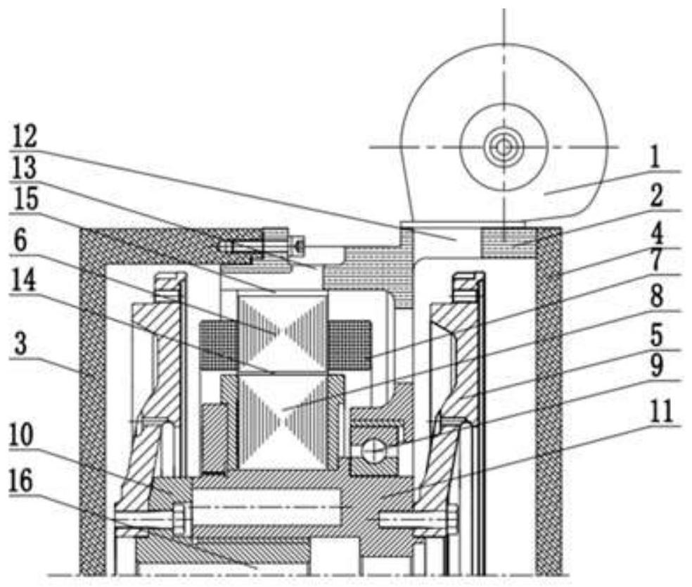
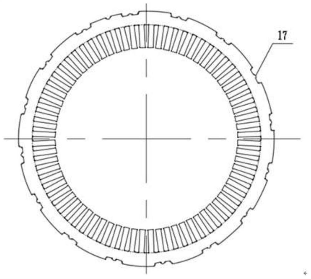
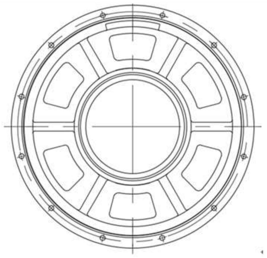
[0012] Such as figure 1 As shown, the present invention includes blower 1, casing 2, left end cover 3, right end cover 4, flywheel 5, stator core 6, winding 7, rotor 8, bearing 9, rotating shaft left end 10, rotating shaft right end 11, air inlet 12, outlet Tuyere 13 forms. The blower 1 is fixed at the air inlet 12 of the casing 2. A stator core 6 is arranged inside the casing 2, and a winding 7 is embedded inside the stator core 6. The casing 2 is connected to the right end 11 of the rotating shaft through a bearing 9, and the right end of the rotating shaft is covered with a The rotor 8 and the permanent magnet are assembled inside the rotor. The left end 10 of the rotating shaft and the right end 11 of the rotating shaft are connected by splines, and are connected with the flywheel 5 respectively. The l...


PUM


Abstract

The invention relates to an electric vehicle permanent magnet motor with a stator and rotor integrated ventilation cooling structure, which comprises a casing, a left end cover, a flywheel, a stator core, a winding, a rotor, a bearing and a rotating shaft, and the ventilation cooling structure comprises an air blower, an air inlet, an air outlet, an air gap, a rotating shaft ventilation duct and a stator ventilation duct, air enters the motor from the air inlet by the air blower, respectively enters the casing ventilation opening, the rotor shaft ventilation duct, the air gap and the stator ventilation duct, and then flows out of the motor from the air outlet on the casing to achieve the purpose of circulating cooling, the stator ventilation duct consists of a plurality of welded junctions of the casing and the stator core, and the welded junctions are distributed on the circumference of the stator core; the rotating shaft ventilating duct comprises a through hole formed in the center of the rotating shaft; the machine shell ventilation opening comprises a plurality of fan-shaped holes formed in the connecting face of the machine shell and the bearing.

Description

technical field [0001] The invention belongs to the field of permanent magnet motors for electric vehicles, and in particular relates to a permanent magnet motor for electric vehicles with a stator-rotor integrated ventilation and cooling structure. Background technique [0002] Permanent magnet motors have the advantages of high power density, high efficiency, and wide speed range, and are widely used in the electric vehicle industry. The performance of the motor will directly affect the efficiency of the electric vehicle drive system and the overall work compactness. The high-speed permanent magnet synchronous motor used in electric vehicles has become a trend, and the consequent rotor loss has also greatly increased. While pursuing the reduction of rotor loss, more efficient cooling structures are also required more strongly. In view of the high power density, small size, light weight, high efficiency, and high-speed development trend of the current electric vehicle dri...

Claims


Application Information

Patent Timeline
Patent Type & Authority Applications(China)
IPC IPC(8): H02K9/04H02K5/20H02K1/20H02K1/32
CPCH02K9/04H02K5/207H02K1/20H02K1/32Y02T10/64
Inventor 王晓远梁慧静李娜
Owner TIANJIN UNIV
Learn More