High-bandwidth SIW circularly polarized filtering antenna

A filter antenna and circular polarization technology, which is applied in the field of satellite wireless communication, can solve the problems of narrow axial ratio bandwidth and gain bandwidth, which are unfavorable for wide application, and achieve wide gain bandwidth and axial ratio bandwidth, and solve the effect of narrow bandwidth

Active Publication Date: 2022-04-22
XIDIAN UNIV
View PDF6 Cites 0 Cited by
  • Summary
  • Abstract
  • Description
  • Claims
  • Application Information

AI Technical Summary

Problems solved by technology

However, the high-order mode with complex electric field distribution is not conducive to wide application, and the narrow axial ratio bandwidth and gain bandwidth still need to be further improved

Method used


Image

  • High-bandwidth SIW circularly polarized filtering antenna
  • High-bandwidth SIW circularly polarized filtering antenna
  • High-bandwidth SIW circularly polarized filtering antenna

Examples


Embodiment 1

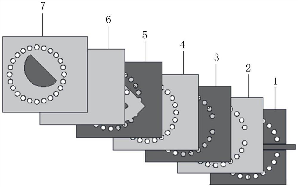
[0043] See figure 1 , figure 1 It is a schematic structural diagram of a high-bandwidth SIW circularly polarized filter antenna provided by an embodiment of the present invention, which includes: a first metal layer 1, a first dielectric layer 2, a second metal layer 3, and a second dielectric layer from bottom to top layer 4, the third metal layer 5, the third dielectric layer 6 and the fourth dielectric layer 7; wherein,

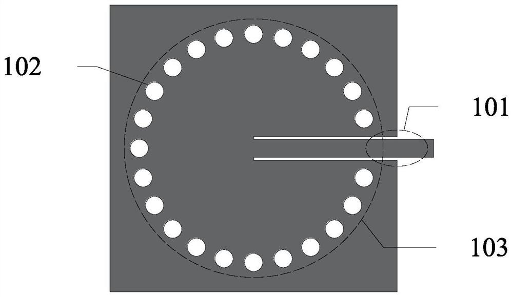
[0044] A coplanar waveguide structure 101 is disposed on the first metal layer 1;

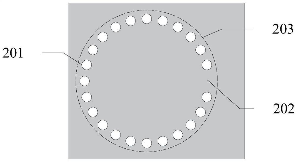
[0045] The first dielectric layer 2 is provided with a plurality of first through holes 201, and the plurality of first through holes 201 are uniformly arranged to form a first SIW resonant cavity 203 with an input window 202; In the direction of the plane where the metal layer 1 is located, the orthographic projection of the input window 202 overlaps with the orthographic projection of the coplanar waveguide structure 101;

[0046] Several radiation windows 301 are prov...

Embodiment 2

[0076] Next, three-dimensional modeling and performance simulation of the circularly polarized filter antenna provided by the present invention are performed through simulation software to verify the beneficial effect of the high-bandwidth SIW circularly polarized filter antenna provided by the present invention.

[0077] 2.1 Test platform:

[0078] The simulation test is carried out with the three-dimensional electromagnetic full-wave simulation software HFSS_18.0.

[0079] 2.2 Simulation content

[0080] The resonant frequency of the first microstrip patch 502 used in this simulation test is 13.5 GHz, and the main mode is used as the working mode. The second dielectric layer 4 is made of duroid 5880 Rogers material with a thickness of 1.524 mm. The diameter of the second through hole 401 is The central angle between two adjacent second through holes 401 is 15 degrees.

[0081] The second SIW resonant cavity 402 is a circular SIW cavity with a center frequency f r The calc...


PUM


Abstract

The invention discloses a high-bandwidth SIW circularly polarized filtering antenna which sequentially comprises a first metal layer, a first dielectric layer, a second metal layer, a second dielectric layer, a third metal layer, a third dielectric layer and a fourth dielectric layer from bottom to top. Wherein the second metal layer is provided with a plurality of radiation windows; a semicircular gap is formed in the third metal layer, and a semicircular first microstrip patch is nested in the semicircular gap; and a third SIW resonant cavity is formed on the fourth dielectric layer, a plurality of second microstrip patches correspondingly overlapped with the radiation windows are arranged in the third SIW resonant cavity, and the second microstrip patches have a certain deflection angle relative to the vertical direction. According to the high-bandwidth SIW circularly polarized filtering antenna provided by the invention, the radiation characteristics of circular polarization and band-pass filtering are realized on the basis of miniaturization, in addition, relatively wide gain bandwidth and axial ratio bandwidth are also obtained, and the problems of relatively narrow bandwidth and limited application range of a circularly polarized filtering antenna in the prior art are solved.

Description

technical field [0001] The invention belongs to the technical field of satellite wireless communication, and in particular relates to a high-bandwidth SIW circular polarization filter antenna. Background technique [0002] Satellite communication is the use of artificial earth satellites as relay stations to transmit wireless electromagnetic waves, thereby realizing communication between two or more earth stations. Among them, the antenna, as a component for transmitting or receiving electromagnetic waves, plays an important role in the satellite communication system. With the development of satellite communication technology, in order to cope with the problems of frequency band congestion, polarization mismatch and narrow bandwidth encountered in satellite communication, researchers have designed a circularly polarized antenna that can cover X-band and Ku-band at the same time. Furthermore, in order to meet the miniaturization and increasingly stringent requirements on cir...

Claims


Application Information

Patent Timeline
Patent Type & Authority Applications(China)
IPC IPC(8): H01Q9/04H01Q5/10H01Q1/52
CPCH01Q9/0414H01Q9/0428H01Q1/52H01Q5/10
Inventor 董刚姚奕彤朱樟明杨银堂
Owner XIDIAN UNIV
Why Eureka
Try Eureka