Eureka AIR delivers breakthrough ideas for toughest innovation challenges, trusted by R&D personnel around the world.

Solar photo-thermal loop heat pipe air conditioner heating system and control method thereof

A loop heat pipe and solar energy technology, which is applied in air conditioning systems, heating and ventilation control systems, heating methods, etc., can solve the problem of large investment in heating systems, high energy consumption, and lower COP value of air source heat pump heating systems, etc. problem, to achieve the effect of improving the heating energy efficiency of the air conditioner, increasing the heating capacity, increasing the heating capacity and heating energy efficiency

Active Publication Date: 2022-04-22
TAIYUAN DESIGN RES INST FOR COAL IND
View PDF17 Cites 0 Cited by
  • Summary
  • Abstract
  • Description
  • Claims
  • Application Information

AI Technical Summary

Problems solved by technology

Due to the single use of the air source heat pump system for heating in winter, the number of air source heat pumps in the heating system is large, and the investment in the heating system is large.
And when the outdoor temperature is lower than -15°C, the COP value of the air source heat pump heating system is greatly reduced, resulting in high energy consumption and other problems

Method used


Image

  • Solar photo-thermal loop heat pipe air conditioner heating system and control method thereof
  • Solar photo-thermal loop heat pipe air conditioner heating system and control method thereof
  • Solar photo-thermal loop heat pipe air conditioner heating system and control method thereof

Examples


Embodiment Construction

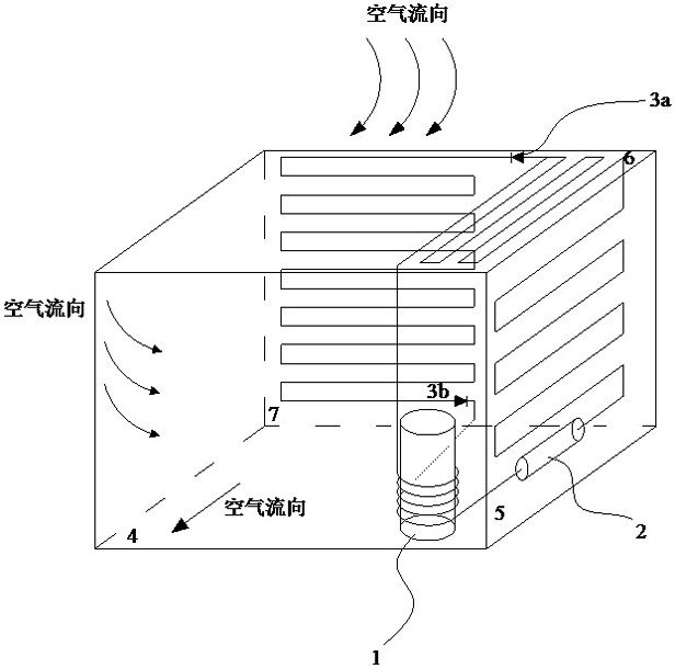
[0041] like Figure 1 to Figure 4 As shown, a solar photothermal loop heat pipe air-conditioning and heating system of the present invention includes an air-conditioning outdoor unit 4, and the side, top surface, and back of the air-conditioning outdoor unit 4 are respectively provided with a heat pipe side evaporation plate 5 and a heat pipe top surface evaporation plate. 6 and the condensing network frame 7 on the back of the heat pipe, wherein the heat pipe side evaporator plate 5, the heat pipe top surface evaporator plate 6 and the heat pipe back condensing network frame 7 are all provided with loop heat pipes, and the inside of the air conditioner outdoor unit 4 is provided with a DC frequency conversion compression machine 1;

[0042] One end of the heat pipe on the heat pipe side evaporation plate 5 is connected to one end of the heat pipe on the heat pipe top surface evaporation plate 6, and the other end of the heat pipe on the heat pipe side evaporation plate 5 is c...


PUM

PropertyMeasurementUnit
Resistanceaaaaaaaaaa
Radiation intensityaaaaaaaaaa

Abstract

The invention provides a solar photo-thermal loop heat pipe air conditioner heating system and a control method thereof, and belongs to the technical field of solar photo-thermal loop heat pipe air conditioner systems. The hardware structure of the solar photo-thermal loop heat pipe air conditioner heating system is improved; according to the technical scheme adopted for solving the technical problems, the loop heat pipes are arranged on a heat pipe side face evaporation plate, a heat pipe top face evaporation plate and a heat pipe back face condensation net frame of the air conditioner outdoor unit, and the two ends of the heat pipes on the heat pipe top face evaporation plate are connected with the heat pipes on the heat pipe side face evaporation plate and the heat pipe back face condensation net frame respectively. Meanwhile, a direct-current variable-frequency compressor is connected with the heat pipes arranged on the heat pipe side face evaporation plate, the heat pipe top face evaporation plate and the heat pipe back face condensation net rack, and heat pipe working medium one-way valves are installed at the two ends of the heat pipes on the heat pipe back face condensation net rack respectively; a loop heat pipe liquid storage capillary evaporation pipe section is mounted on the heat pipe, connected with the direct-current variable-frequency compressor, of the heat pipe side evaporation plate; the invention is applied to air-conditioning water heaters and heating machines.

Description

technical field [0001] The invention discloses a solar photothermal loop heat pipe air conditioner heating system and a control method thereof, belonging to the technical field of solar photothermal loop heat pipe air conditioner heating. Background technique [0002] With the national and local restrictions on the use of coal-fired boilers, the use of coal-fired boilers below 20 steam tons / h has been strictly prohibited. More and more coal mine heating methods are replaced by gas boilers, solar energy, soil source heat pumps, air source heat pumps, and electric heating. [0003] Due to the large area and high floor height of buildings such as canteens and machine repair workshops in coal mine buildings, the heating load in winter is very large. Now some canteens, machine repair rooms and other buildings in coal mines have begun to use air source heat pump systems for heating in winter. Due to the single use of the air source heat pump system for heating in winter, the num...

Claims


Application Information

Patent Timeline
IPC IPC(8): F24F1/0003F24F1/06F24F5/00F24F11/86F24F13/30
CPCF24F1/0003F24F1/06F24F5/001F24F5/0046F24F11/86F24F13/30Y02A30/272
Inventor 冯瑞峰龚永平莫亚辛梁思源
Owner TAIYUAN DESIGN RES INST FOR COAL IND
Why Eureka
Eureka Blog
Learn More