
Gravity locking type clamping device and clamping method

A clamping device and locking technology, applied in the direction of chucks, manufacturing tools, manipulators, etc., can solve problems such as excessive or small clamping force, excessive clamping force, size and gravity differences, etc., to achieve improved Stability, the effect of avoiding too much or too little clamping force

Active Publication Date: 2022-04-22
SHENZHEN DACHENG PRECISION EQUIP CO LTD
View PDF15 Cites 0 Cited by
  • Summary
  • Abstract
  • Description
  • Claims
  • Application Information

AI Technical Summary

Problems solved by technology

[0002] In the prior art, the clamping of the lithium battery mostly adopts an active clamping mechanism, which directly applies a fixed clamping force to the lithium battery to realize the clamping of the lithium battery. This solution only uses the lithium battery in an ideal state, and the actual Multiple lithium batteries in the same batch of products will also have differences in size and gravity. If a fixed clamping force is used for clamping, it is easy to have problems with too large or too small clamping force
In particular, for the active clamping mechanism that clamps multiple lithium batteries at the same time, there are differences in thickness and gravity between different lithium batteries. The current active clamping mechanism uses the same clamping force for each lithium battery, which is easy Some lithium batteries have problems with too large or too small clamping force, which in turn affects the production quality of lithium batteries

Method used


Image

  • Gravity locking type clamping device and clamping method
  • Gravity locking type clamping device and clamping method
  • Gravity locking type clamping device and clamping method

Examples


Embodiment Construction

[0026] The present invention will be further described in detail below through specific embodiments in conjunction with the accompanying drawings. Wherein, similar elements in different implementations adopt associated similar element numbers. In the following implementation manners, many details are described for better understanding of the present application. However, those skilled in the art can readily recognize that some of the features can be omitted in different situations, or can be replaced by other elements, materials, and methods. In some cases, some operations related to the application are not shown or described in the description, this is to avoid the core part of the application being overwhelmed by too many descriptions, and for those skilled in the art, it is necessary to describe these operations in detail Relevant operations are not necessary, and they can fully understand the relevant operations according to the description in the specification and genera...


PUM


Abstract

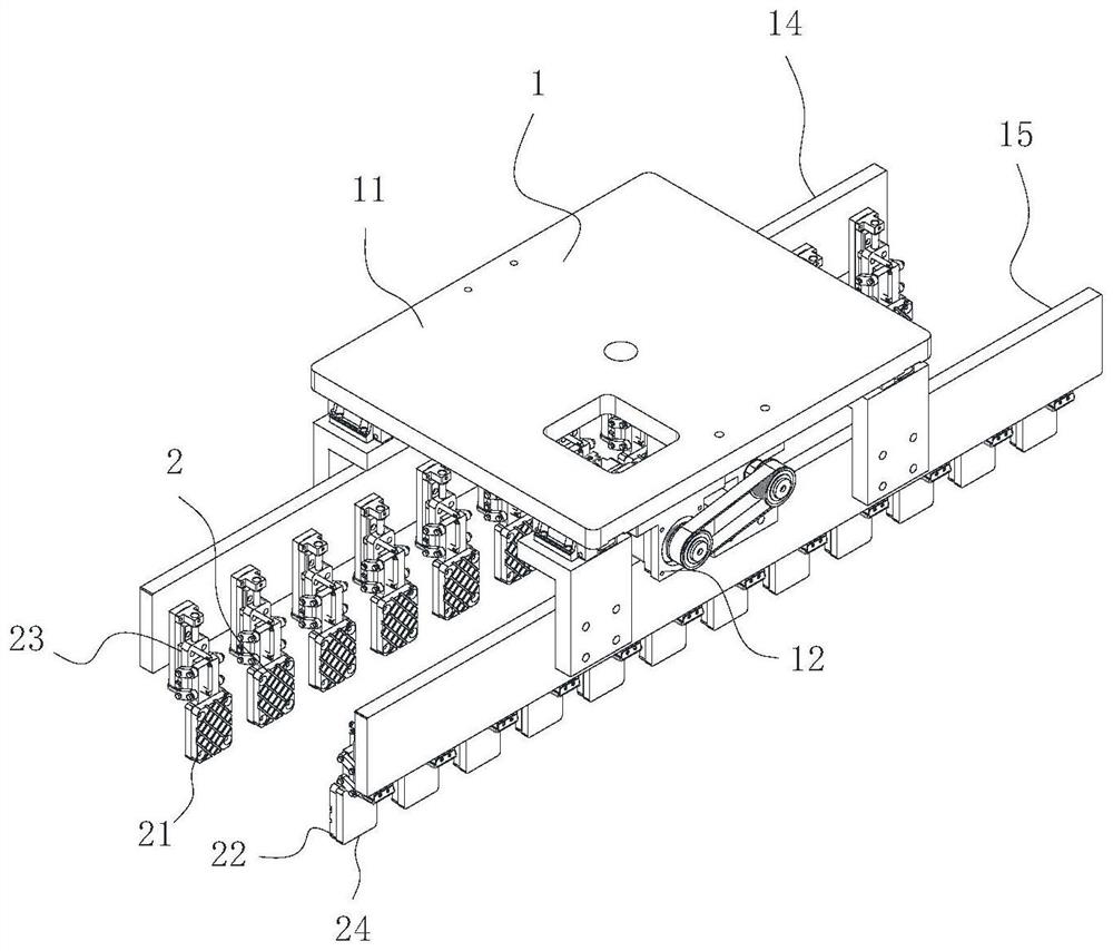
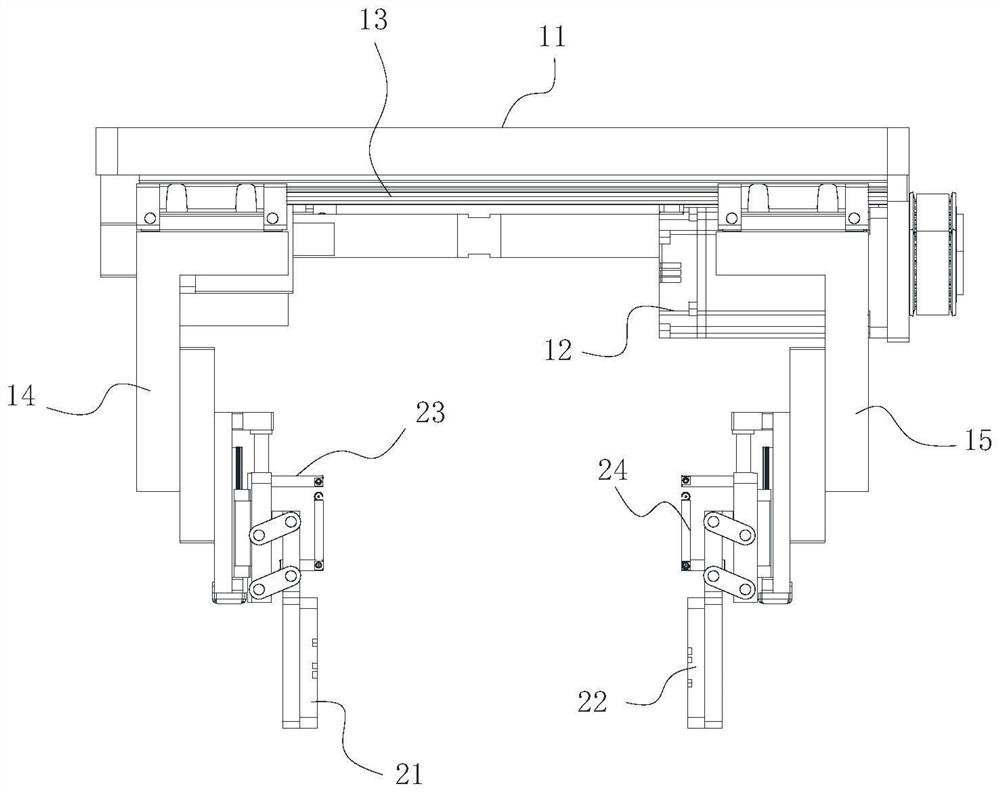
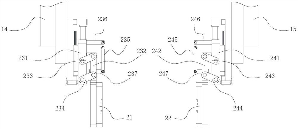
The invention discloses a gravity locking type clamping device and a clamping method. The gravity locking type clamping device comprises a driving assembly and a clamping assembly, and the multiple clamping assemblies comprise first clamping faces, second clamping faces, first plane four-bar mechanisms and second plane four-bar mechanisms, the first clamping faces are arranged on the first connecting rods, and the second clamping faces are arranged on the second connecting rods. In the plurality of clamping assemblies, each clamping assembly is internally provided with the first plane four-bar mechanism and the second plane four-bar mechanism, so that the first plane four-bar mechanism and the second plane four-bar mechanism can convert the gravity of the lithium battery into auxiliary clamping force when the lithium battery is clamped by each pair of first clamping surface and second clamping surface; the clamping force output by the driving mechanism does not need to be too large, compensation can be conducted through auxiliary clamping force, then self-adaptive clamping can be conducted on different lithium batteries at the same time, the clamping stability is improved, and meanwhile the problem that the clamping force is too large or too small can be solved.

Description

technical field [0001] The invention relates to the technical field of lithium battery production, in particular to a gravity locking clamping device and a clamping method. Background technique [0002] In the prior art, the clamping of the lithium battery mostly adopts an active clamping mechanism, which directly applies a fixed clamping force to the lithium battery to realize the clamping of the lithium battery. This solution only uses the lithium battery in an ideal state, and the actual There will also be differences in size and gravity among multiple lithium batteries in the same batch of products. If a fixed clamping force is used for clamping, it is easy to have problems with too large or too small clamping force. In particular, for the active clamping mechanism that clamps multiple lithium batteries at the same time, there are differences in thickness and gravity between different lithium batteries. The current active clamping mechanism uses the same clamping force f...

Claims


Application Information

Patent Timeline
IPC IPC(8): B25J15/00B25J15/02
CPCB25J15/0052B25J15/0206B25J15/0253
Inventor 张孝平文青松汪毅
Owner SHENZHEN DACHENG PRECISION EQUIP CO LTD
Learn More