
Defect detection method and detection system for mask plate

A technology of defect detection and reticle, which is applied in the field of defect detection method and detection system of reticle, which can solve the problems of limited resolution ability, curved surface mirror cannot detect defects, etc., and achieve the effect of improving resolution

Pending Publication Date: 2022-04-19
CHANGCHUN INST OF OPTICS FINE MECHANICS & PHYSICS CHINESE ACAD OF SCI
View PDF0 Cites 0 Cited by
  • Summary
  • Abstract
  • Description
  • Claims
  • Application Information

AI Technical Summary

Problems solved by technology

The disadvantage of this method is that due to the existence of the flat mirror, the curved mirror cannot be too close to the mask for defect detection, which limits the receiving NA (numerical aperture, numerical aperture) of the defect scattered light and limits the resolution of the system.

Method used


Image

  • Defect detection method and detection system for mask plate
  • Defect detection method and detection system for mask plate
  • Defect detection method and detection system for mask plate

Examples


Embodiment 1

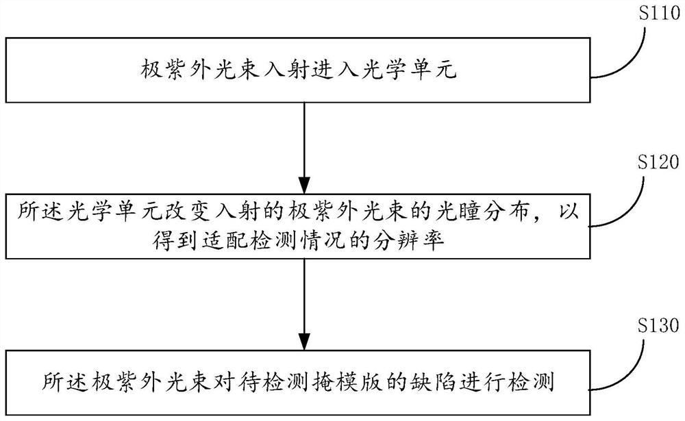
[0034] see figure 1 , a flow chart of the steps of the defect detection method for the reticle provided by the present application, including the following steps:

[0035] Step S110: the EUV light beam is incident into the optical unit.

[0036] Step S120: the optical unit changes the pupil distribution of the incident EUV light beam to obtain a resolution adapted to the detection situation.

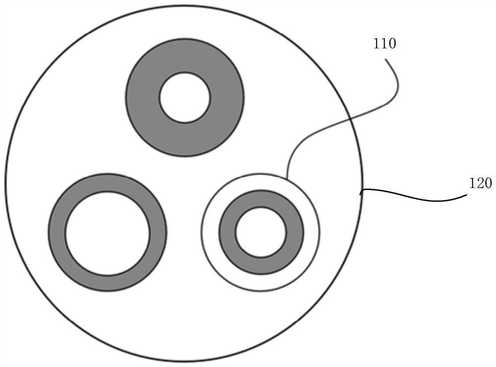
[0037] see figure 2 , is a schematic structural diagram of the optical unit provided by an embodiment of the present application.

[0038] In this embodiment, the optical unit includes coherent plates 110 with different coherence factors. The coherent plates 110 are mounted on a rotating disk 120 , and the rotating disk 120 is positioned at a proper position in the optical path by the rotation of the rotating disk 120 .

[0039] It can be understood that the coherent plates with different coherence factors are pre-installed on a rotating disk, and according to the structure of the op...

Embodiment 2

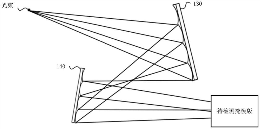
[0046] see again image 3 The present application also provides a defect detection system for a reticle, including: a light source module, including a light source for providing an extreme ultraviolet light beam; an optical unit, which can change the pupil distribution of the incident extreme ultraviolet light beam, to A resolution adapted to the detection situation is obtained; a detection unit is provided with a reticle to be detected, and the extreme ultraviolet light beam detects defects of the reticle to be detected.

[0047] In some of the embodiments, the optical unit includes coherent plates with different coherence factors, the coherent plates are installed on a rotating disk, and the rotating disk is positioned at a proper position in the optical path through the rotation of the rotating disk.

[0048]It can be understood that the coherent plates with different coherence factors are pre-installed on a rotating disk, and according to the structure of the optical path,...


PUM


Abstract

According to the defect detection method and system for the mask plate, the extreme ultraviolet light beam enters the optical unit in an incident mode, the optical unit changes pupil distribution of the incident extreme ultraviolet light beam so as to obtain the resolution ratio matched with the detection condition, the extreme ultraviolet light beam detects the defect of the mask plate to be detected, and the detection result is more accurate. According to the defect detection method and detection system for the mask plate, provided by the invention, the pupil distribution, namely the pupil function, is changed according to the requirements of different detection conditions on the resolution, so that the resolution of defect detection is improved.

Description

technical field [0001] The invention belongs to optical detection technology, and in particular relates to a defect detection method and detection system of a reticle. Background technique [0002] Defect-free EUV (extremely ultraviolet) mask preparation is one of the key issues restricting EUV lithography to mass production. Therefore, EUV mask defect detection is the key core technology to realize EUV lithography. EUV mask defects can be divided into amplitude defects and phase defects, among which phase defects are the most important defects. Because the phase defect is caused by the distortion of the multi-layer structure of the EUV mask, it needs to penetrate the multi-layer structure for detection. The traditional detection method based on deep ultraviolet or ultraviolet cannot meet this requirement, and it needs to use the working wavelength for detection. [0003] To this end, the researchers used the EUV-based light source to penetrate the multilayer structure for...

Claims


Application Information

Patent Timeline
IPC IPC(8): G01N21/95G01N21/88
CPCG01N21/95G01N21/8806
Inventor 王丽萍张旭金春水
Owner CHANGCHUN INST OF OPTICS FINE MECHANICS & PHYSICS CHINESE ACAD OF SCI
Learn More