
Cold compress mask with temperature control function

A mask and functional technology, applied in the field of cold compress masks with temperature control function, can solve the problems of cold compress masks having no temperature adjustment function and inconvenient use, etc., and achieve the effects of controllable cold compress temperature, convenient use, and continuous low temperature maintenance.

Pending Publication Date: 2022-04-19
PEOPLES HOSPITAL OF ZHENGZHOU
View PDF0 Cites 0 Cited by
  • Summary
  • Abstract
  • Description
  • Claims
  • Application Information

AI Technical Summary

Problems solved by technology

[0003] The prior art uses a cold compress mask for cold compress treatment, but the cold compress mask of the prior art does not have the function of temperature adjustment, and needs to be replaced manually after a period of use, which is not convenient to use. In order to solve this technical problem, a kind of Temperature control function cold compress mask

Method used


Image

  • Cold compress mask with temperature control function
  • Cold compress mask with temperature control function
  • Cold compress mask with temperature control function

Examples


Embodiment 1

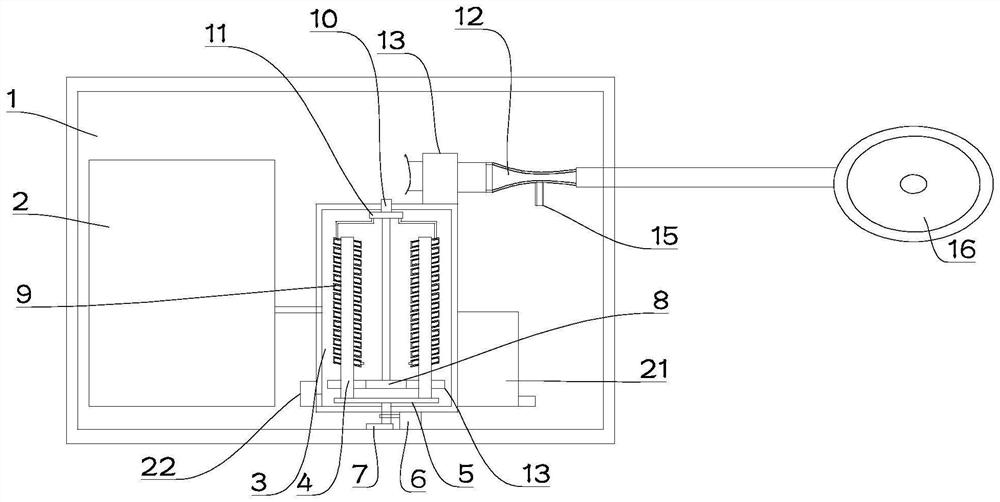
[0026] see Figure 1~3 , in Embodiment 1 of the present invention, a structural diagram of a cold compress mask with a temperature control function provided for the embodiment of the present invention, including: a temperature control device 1 and a mask shell 16, and the mask shell 16 is used for snapping on The face; the inside of the mask shell 16 is provided with a circulation chamber 17;

[0027] The liquid storage tank 2, the freezer tank 3 and the transition tank 21 arranged inside the temperature control device 1; the liquid storage tank 2 is used to store fluid, the freezer tank 3 is used to cool down the fluid, and the liquid storage tank 2 is used for Input the cooled fluid into the transition tank 21;

[0028] The mixing part arranged inside the temperature control device 1, the two input ends of the mixing part communicate with the interior of the transition tank 21 and the liquid storage tank 2 respectively, and the output end of the mixing part communicates wit...

Embodiment 2

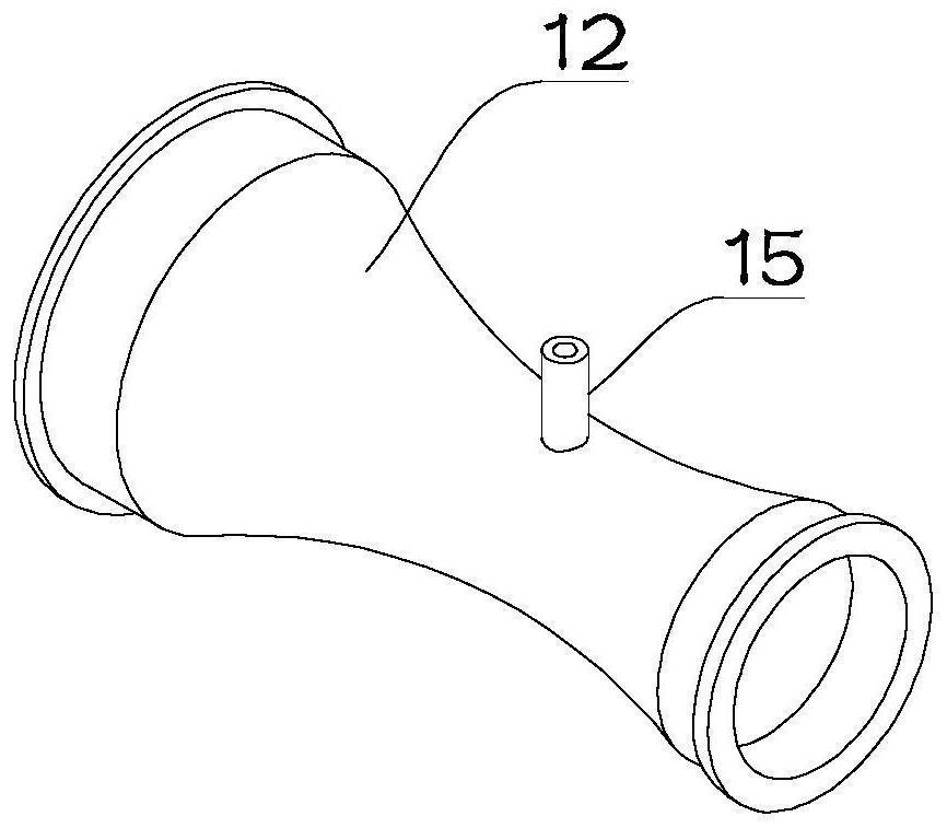
[0032] see Figure 1~3 The main difference between this embodiment 2 and embodiment 1 is that the mixing part can also be set as a venturi tube 12, and the input end of the venturi tube 12 is connected to the liquid storage tank 2 through a pipeline, and the venturi tube 12 The output end communicates with the circulation chamber 17, and the waist of the Venturi tube 12 is provided with a communication pipe 15 communicating with its interior, and the communication pipe 15 communicates with the interior of the transition box 21 through a pipeline, and a regulating valve is arranged on the communication pipe 15, and the The regulating valve is used to adjust the opening size of the communication pipe 15 .

[0033] In order to provide power for the fluid flow, the input end of the venturi tube 12 is provided with a feed pump 13 , and the input end of the feed pump 13 communicates with the inside of the liquid storage tank 2 through a pipeline. In this way, the fluid flow provide...


PUM


Abstract

The invention is suitable for the technical field of beauty equipment, and provides a cold compress mask with a temperature control function. Comprising a temperature control device and a mask shell, a circulating cavity is formed in the mask shell; the liquid storage box, the freezing box and the transition box are arranged in the temperature control device; the liquid storage box is used for storing fluid, the freezing box is used for cooling the fluid, and the liquid storage box is used for inputting the cooled fluid into the transition box; the mixing component is arranged in the temperature control device, the two input ends of the mixing component are communicated with the interiors of the transition box and the liquid storage box respectively, and the output end of the mixing component is communicated with the circulating cavity in the mask shell through a pipeline; the mixing component can control the opening proportion of the two input ends; the requirement for controllable cold compress temperature is met, the low temperature can be continuously maintained, and use is convenient.

Description

technical field [0001] The invention relates to the technical field of beauty equipment, in particular to a cold compress mask with a temperature control function. Background technique [0002] Due to the abundant blood supply and loose tissue of the maxillofacial region, the postoperative swelling reaction is also more obvious. In clinical practice, local pressure and ice compress are often needed to reduce the postoperative reaction. [0003] The prior art uses a cold compress mask for cold compress treatment, but the cold compress mask of the prior art does not have the function of temperature adjustment, and needs to be replaced manually after a period of use, which is not convenient to use. In order to solve this technical problem, a kind of Temperature control function cold compress mask. Contents of the invention [0004] The object of the present invention is to provide a cold compress face mask with temperature control function to solve the problems raised in the...

Claims


Application Information

Patent Timeline
Patent Type & Authority Applications(China)
IPC IPC(8): A61F7/00B01F25/312
CPCA61F7/00A61F7/0085A61F2007/0003A61F2007/0056
Inventor 刘玮玮宋银森李正斌张思森
Owner PEOPLES HOSPITAL OF ZHENGZHOU
Learn More