Inspection instrument with real-time display function

A technology of real-time display and inspection instrument, applied in the field of inspection instrument, can solve the problems of single data source detection, poor intuition, single type of result output, etc., achieve good scalability and reusability, improve efficiency, and easy and accurate positioning Effect

Pending Publication Date: 2022-04-15
易思维(杭州)科技有限公司
View PDF2 Cites 0 Cited by
  • Summary
  • Abstract
  • Description
  • Claims
  • Application Information

AI Technical Summary

Problems solved by technology

CN112002031A discloses a kind of unmanned aerial vehicle-based catenary fully automatic intelligent inspection system and inspection method, which provides a system and method for automatic detection of catenary status by unmanned aerial vehicles, but due to the use of unmanned aerial vehicles to collect data , after returning to the voyage, the method of analysis and processing by the working machine is not real-time, and the inspection efficiency is low; at the same time, the test results are written in text, which is not intuitive, and there is no other track-related information for auxiliary reference, so it is difficult to accurately locate Point of failure and cause of failure
CN111309845A discloses a method and system for displaying macroscopic situation data of rail transit road network, which proposes a method for reconstructing and modeling multi-source data of macroscopic situation of rail transit road network, and finally displaying it in the same road network diagram , provides an intuitive and comprehensive information display for the regional road network, and enables railway operators to control the macroscopic situation of the road network in the whole region from a global perspective. However, the field of catenary inspection is currently limited to a single data source The detection and output of a single type of result

Method used


Image

  • Inspection instrument with real-time display function
  • Inspection instrument with real-time display function
  • Inspection instrument with real-time display function

Examples


Embodiment Construction

[0030] The technical solutions of the present invention will be described in detail below in conjunction with the accompanying drawings and embodiments.

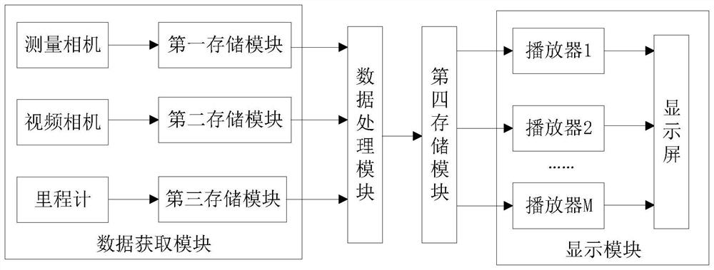
[0031] Such as figure 1 As shown, a patrol instrument with real-time display function includes a data acquisition module, a data processing module and a display module;

[0032] The data acquisition module includes a measurement camera, a video camera and an odometer that can be synchronized and continuously triggered at a fixed frequency; the measurement camera is used to collect the picture data required to solve the static parameters of the catenary, and calculate the static parameters of the catenary based on the picture data, and will The calculation result is stored in the first storage module; the field of view of the video camera is greater than the field of view of the measuring camera, and is used to collect video pictures and store them in the second storage module; Corresponding mileage data, and store it in the...


PUM


Abstract

The invention discloses an itinerant detector with a real-time display function. The itinerant detector comprises a data acquisition module, a data processing module and a display module, the data acquisition module comprises a measurement camera, a video camera and a speedometer which can be synchronized and continuously triggered at a fixed frequency; the measuring camera can obtain and store static parameters of the overhead line system; the field of view of the video camera is larger than that of the measurement camera, and the video camera is used for collecting and storing video pictures; the odometer is used for collecting and storing mileage data; when the video data and the static parameters of the contact network in the storage module reach a preset number, the video data and the static parameters are packaged and transmitted to a fourth storage module; the display module comprises at least two player modules, the player modules respectively acquire the video packets from the fourth storage module and alternately complete loading of the video packets and playing of the video packets on a display screen in parallel according to mileage or time, and each frame is marked with mileage data and contact network static parameters. The inspection instrument can display a detection result in real time, the display result is more visual, and a fault position is easy to locate.

Description

technical field [0001] The invention relates to the field of visual detection, in particular to a patrol instrument with real-time display function. Background technique [0002] Catenary is the most important power supply network of my country's electrified railway, and its suspension status is directly related to the normal power supply of electrified railway locomotives. Therefore, carrying out catenary inspection work has important practical significance and urgent needs for ensuring the normal operation of my country's electrified railways. [0003] At present, the common detection tools are mostly hand-held inspection equipment. Since they can only be used for handheld equipment and single-point measurement, they cannot take into account the requirements of detection efficiency and accuracy. In addition, the catenary operation and maintenance department needs to perform static review and inspection of dynamic detection exceeding the limit. Confirmation, because there ...

Claims


Application Information

Patent Timeline
IPC IPC(8): G07C1/20H04N7/18
Inventor 李章虢薇高圩方建胜庄洵
Owner 易思维(杭州)科技有限公司
Why Eureka
Try Eureka