Driving control system and method and electronic equipment
A technology of driving control and driving modules, which is applied in the field of electronics, can solve problems affecting user experience and the structure of electronic equipment is not light enough, and achieve the effect of facilitating the layout of space structure, reducing the number of hardware structures, and improving user experience
- Summary
- Abstract
- Description
- Claims
- Application Information
AI Technical Summary
Problems solved by technology
Method used
Image
Examples
Embodiment 2
[0051] Embodiment 2 provides a driving control method, Figure 5 Shown is a structural flow chart of a drive control method according to an embodiment of the present invention, the method comprising:
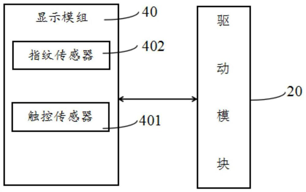
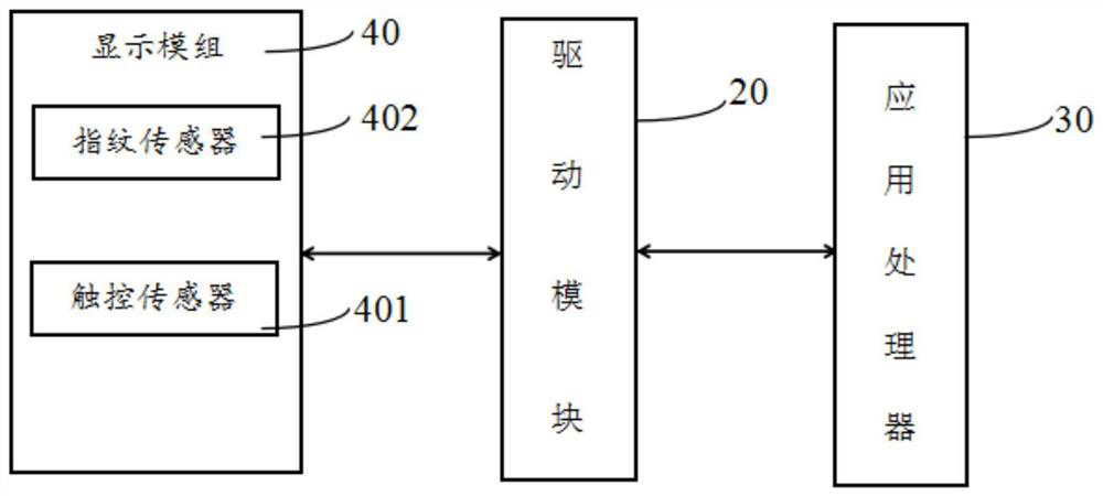
[0052] S20. Driving the display panel to display in the display phase, and driving the touch sensor to work in the line blanking phase.
[0053] The method described in this embodiment implements image display and touch sensing in a time-division multiplexing manner, which reduces signal interaction interference and improves user experience.
Embodiment 3
[0054] Embodiment 3 provides a driving control method, Figure 6 Shown is a structural flow chart of a drive control method according to an embodiment of the present invention, as Figure 6 As shown, the method also includes:
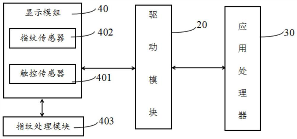
[0055] The fingerprint sensor is driven to work during the line blanking phase.
[0056] The method described in this embodiment implements image display and fingerprint collection in a time-division multiplexing manner, which reduces signal interaction interference and improves user experience.
[0057] As a preferred implementation of the present invention, the line blanking phase can be divided into at least two time periods, at least one time period is used for fingerprint recognition, and at least one time period is used for driving the touch sensor, such as 1, 3 , 5, 7 time periods are used for fingerprint recognition, 2, 4, 6, 8 time periods are used to drive the touch sensor to work.
Embodiment approach
[0058] As a preferred embodiment of the present invention, the method further includes the step of storing the fingerprint information, collecting the fingerprint information according to the touch control signal, and sending the fingerprint information to the storage module; obtaining the fingerprint information from the storage module, and comparing the fingerprints When using the fingerprint recognition algorithm for comparison, the comparison result is obtained. The stored fingerprint information can be more than two, and the fingerprint recognition algorithm can be used to perform finger-twisting recognition on the fingerprint information, and the recognition result is output; the recognition result is the case of successful recognition. Next, the control electronics change state. Wherein, the state of the electronic device includes the state of the screen off, the state of the bright screen not unlocked, and the state of the bright screen unlocked.
PUM
 Abstract
Description
Claims
Application Information
 - R&D Engineer
- R&D Manager
- IP Professional
- Industry Leading Data Capabilities
- Powerful AI technology
- Patent DNA Extraction
Browse by: Latest US Patents, China's latest patents, Technical Efficacy Thesaurus, Application Domain, Technology Topic, Popular Technical Reports.
© 2024 PatSnap. All rights reserved.Legal|Privacy policy|Modern Slavery Act Transparency Statement|Sitemap|About US| Contact US: help@patsnap.com


