
Cooling equipment for industrial filtering membrane production

A technology of cooling equipment and filter membrane, which is applied in household refrigeration equipment, lighting and heating equipment, applications, etc., can solve the problems of high energy consumption and low wind utilization rate, and achieve increased cooling efficiency, high utilization rate, and strong pertinence Effect

Pending Publication Date: 2022-04-15
迈博瑞新材料(嘉兴)有限公司
View PDF0 Cites 0 Cited by
  • Summary
  • Abstract
  • Description
  • Claims
  • Application Information

AI Technical Summary

Problems solved by technology

[0003] The filter membranes that need to be sintered, such as metal membranes and ceramic membranes, need to be cooled after sintering. The general cooling device uses a blower to blow the entire cooling chamber to promote the air flow in the entire cooling chamber, thereby taking away the high-temperature gas in the cooling chamber. Cool the filter membrane, but in this way, when blowing air to the entire cooling chamber, only part of the wind can directly blow to the filter membrane, the utilization rate of the wind is low, and the energy consumption is large

Method used


Image

  • Cooling equipment for industrial filtering membrane production
  • Cooling equipment for industrial filtering membrane production
  • Cooling equipment for industrial filtering membrane production

Examples


Embodiment Construction

[0042] The following is a specific embodiment of the present invention and a further description of the technical solutions of the present invention in connection with the accompanying drawings, but the present invention is not limited to these embodiments.

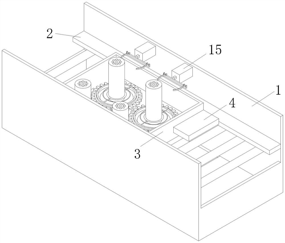
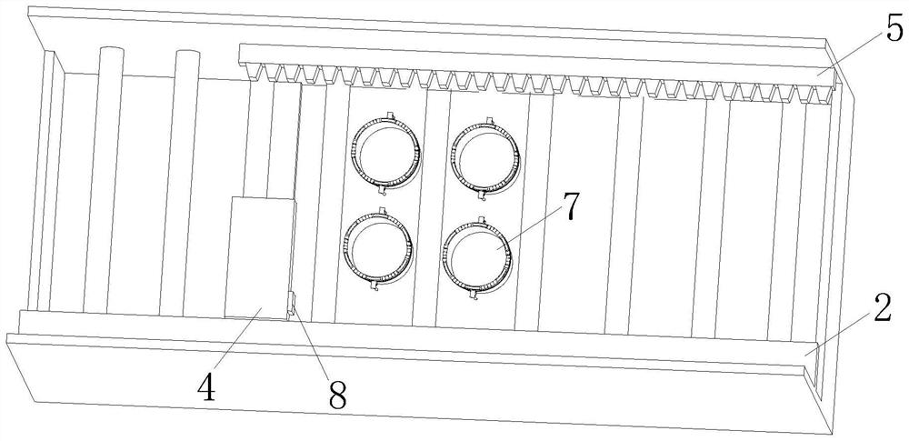
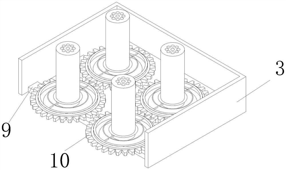
[0043] Such as Figure 1 - Figure 9 As shown, the industrial filter membrane production cooling equipment, including the cooling chamber 1, and the cooling chamber 1 is rotated and connected to the transmission roller, and the inner wall of the cooling chamber 1 is fixed to the finished strip 2, and the inner wall of the cooling chamber 1 is fixed. Both the rack 5, the limit strip 2 and the rack 5 are located above the drive roller, and there is also a casing 3 on the drive roller, and the casing 3 is provided with two rows of flow in the longitudinal direction of the rack 5, and the casing 3. On the side of the restricted strip 2, there is a tooth ring 10 outside, and the air blower is provided below the flow of the flow. twe...


PUM


Abstract

The invention provides cooling equipment for industrial filtering membrane production, belongs to the technical field of filtering membrane production, and solves the problems that when air is blown to a whole cooling chamber, only part of air can be directly blown to a filtering membrane, the air utilization rate is low, and the energy consumption is large. The cooling equipment for industrial filtering membrane production comprises a cooling chamber, a transmission roller is rotationally connected into the cooling chamber, a limiting strip is fixed to the inner wall of one side of the cooling chamber, a rack is fixed to the inner wall of the other side of the cooling chamber, the limiting strip and the rack are both located above the transmission roller, and a basket body is further arranged on the transmission roller; two rows of flow guide mechanisms are arranged in the basket body in the length direction of the rack. The cooling chamber has the advantages that after air in the blower nozzle is guided by the flow guide mechanism, the whole cooling chamber does not need to be blown, the pertinence is higher, the utilization rate is higher, and therefore energy consumption is reduced.

Description

Technical field [0001] The present invention belongs to the field of filter production technology, and involves a cooling device, particularly a cooling device for production of industrial filter membranes. Background technique [0002] Membrane filtration technology refers to a membrane separation technique based on pressure-driven force, also known as membrane filtration technology, an advanced means of depth water treatment. At a certain pressure, when the original liquid flows through the surface, many fine micropores which are densely filled with the surface of the membrane only allow water and small molecular contents to become a permeate, and the volume of the material is greater than the film surface microphilus in the stock solution is The adhesive side of the film is intercepted, and the separation and concentration of the original liquid is achieved. [0003] The filter film such as a metal film and a ceramic film requires cooling after sintering, and the general cooli...

Claims


Application Information

Patent Timeline
Patent Type & Authority Applications(China)
IPC IPC(8): F25D1/00F25D1/02B01D67/00
Inventor 陈冠龙郁春辉谈波
Owner 迈博瑞新材料(嘉兴)有限公司
Learn More