Normal-pressure tool changing cutterhead, shield tunneling machine and tool changing method of normal-pressure tool changing cutterhead
A cutter head and atmospheric pressure technology, which is applied in the fields of earthwork drilling, mechanical equipment, engine components, etc., can solve the problems of low tool change efficiency of the cutter head under atmospheric pressure, and improve the efficiency of shield construction and the safety of tool change. Fast and efficient replacement, more solid sealing effect
- Summary
- Abstract
- Description
- Claims
- Application Information
AI Technical Summary
Problems solved by technology
Method used
Image
Examples
Embodiment 2
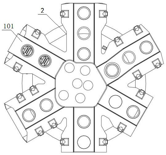
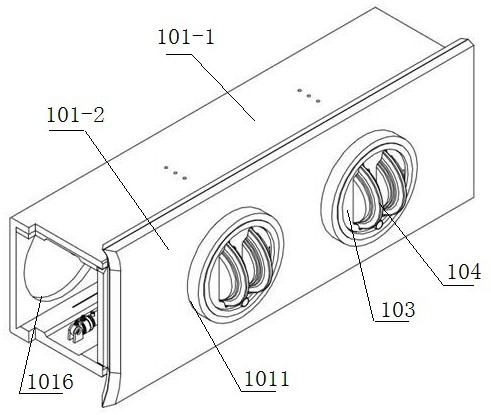
[0038] Example 2, such as figure 2As shown, an atmospheric pressure tool changing cutterhead, on the basis of Embodiment 1, as a preferred solution, the sealed knife chamber 101 is a rectangular shape composed of the front panel 101-1 and the rear shell 101-2 of the cutterhead body 2 Seal the knife compartment. The sealing structure includes a sealing ring groove arranged on the back of the front panel 101-1, a sealing strip 1012 is arranged in the sealing ring groove, and multiple sealing strips 1012 can be arranged according to needs, and the sealing ring groove is arranged on the working surface of the cutter body 2 The through holes on the top are set with the center of the circle to form a uniform seal on the ring surface and improve the sealing effect. As a preferred solution: the front face of the sealed knife chamber 101 is provided with a number of working holes 1011 corresponding to the number of the knife barrel assembly 102, the number of dismounting holes 1016 i...
Embodiment 5
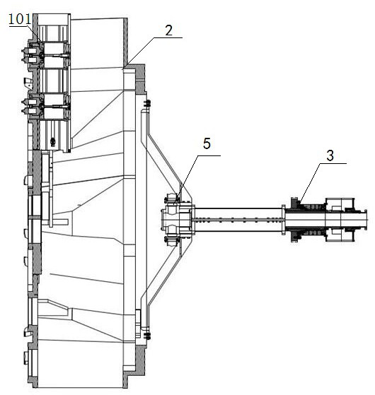
[0046] Embodiment 5: as Figure 9 , 10 As shown, a shield machine includes a hob jaw 4, a main drive 5, and the cutterhead described in Embodiment 4. The main drive 5 is connected to the cutterhead to provide power for the cutterhead to rotate. The main drive 5 is connected with a central rotary joint 3, and the pipelines involved in the atmospheric pressure tool change cutter head 1 are connected through the central rotary joint to avoid pipeline entanglement. The hob jaw 4 cooperates with the cutter 104 on the cutterhead. Specifically: the hob jaw 4 includes a positioning plate 41, the positioning plate is provided with a positioning groove 42 matched with the hob, the back of the positioning plate is provided with a clamping frame 43, the clamping frame can be matched with the tool changing robot, Carry out mechanized intelligent tool change.
Embodiment 6
[0047] Embodiment 6: as Figure 11 As shown, a method for changing a knife of a shield machine described in Embodiment 5, the steps are as follows: including a knife removal process and a knife loading process, wherein the knife removal process is as follows:
[0048] S1: The tool detection device detects the status of the tool online. When the tool is abnormal, the cutter head stops rotating; specifically: the rotation detection device uses a speed sensor to detect whether the tool is rotating. When it is found that the tool cannot perform normal rolling work, the speed sensor returns abnormality The signal is sent to the background controller, and the cutter head stops rotating. The wear detection device uses a hob wear sensor to monitor the wear of the tool. When the wear of the tool exceeds the set value, the hob wear sensor sends back an abnormal signal to the background controller, and the cutter head stops rotating.
[0049] S2: The cutter 104 on the cutter barrel asse...
PUM
 Abstract
Description
Claims
Application Information
 - R&D Engineer
- R&D Manager
- IP Professional
- Industry Leading Data Capabilities
- Powerful AI technology
- Patent DNA Extraction
Browse by: Latest US Patents, China's latest patents, Technical Efficacy Thesaurus, Application Domain, Technology Topic, Popular Technical Reports.
© 2024 PatSnap. All rights reserved.Legal|Privacy policy|Modern Slavery Act Transparency Statement|Sitemap|About US| Contact US: help@patsnap.com


