Camera integrated circuit board welding device

A technology for integrated circuit boards and welding devices, applied to auxiliary devices, welding equipment, auxiliary welding equipment, etc., can solve problems such as desoldering, shaking of integrated circuit boards, short circuits, etc., to reduce the number of uses, save device costs, The effect of improving cleanliness

Inactive Publication Date: 2022-04-15
深圳市晶传科技有限公司
View PDF0 Cites 0 Cited by
  • Summary
  • Abstract
  • Description
  • Claims
  • Application Information

AI Technical Summary

Problems solved by technology

[0003] In the traditional welding process of the integrated circuit board of the camera, since the welding head of the welding machine needs to be in frequent contact with the integrated circuit board during the welding process of the integrated circuit board, the integrated circuit board may shake during the welding process, causing the integrated circuit board to be in the welding process. Desoldering occurs with components such as transistors, resistors, and capacitors, which affects the welding effect of integrated circuit boards
[0004] Due to the high precision of the integrated circuit board of the camera, the traditional integrated circuit board may have the problem of direct contact between the worker's hand and the integrated circuit board on the welding line, and then the worker's hand will leave imprints on the integrated circuit board, leaving traces Sweat and other impurities may cause problems such as poor contact or even short circuit of the integrated circuit board, affecting the conduction of the integrated circuit board

Method used


Image

  • Camera integrated circuit board welding device
  • Camera integrated circuit board welding device
  • Camera integrated circuit board welding device

Examples


Embodiment Construction

[0034] The embodiments of the present invention will be described in detail below with reference to the accompanying drawings, but the present invention can be implemented in many different ways defined and covered by the claims.

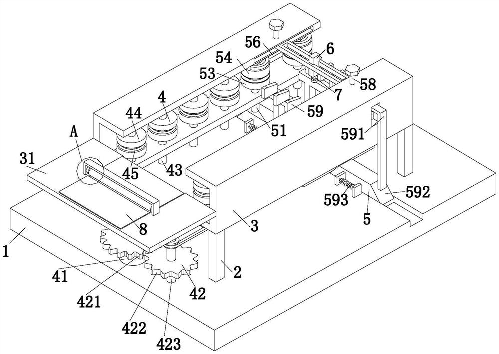
[0035] refer to figure 1 , a camera integrated circuit board welding device, including a welding base plate 1, a support frame 2, a conveying frame 3, a conveying mechanism 4, a limit mechanism 5, a welding part 6 and a welding machine 7, and the upper end of the welding base plate 1 is front and rear. The left and right symmetrically distributed support frames 2 are installed on both sides, and the upper end faces of the left and right adjacent two support frames 2 are jointly installed with a conveying frame 3 with a 匚-shaped structure. A conveying mechanism 4 is installed, and the inside of the two conveying frames 3 and the right side of the upper end surface of the welding bottom plate 1 are jointly installed with a limit mechanism 5. On the op...


PUM


Abstract

The invention relates to the technical field of camera integrated circuit board forming, in particular to a camera integrated circuit board welding device which comprises a welding bottom plate, a supporting frame, a conveying frame, a conveying mechanism, a limiting mechanism, a welding part and a welding machine. The rubber roller rotates to convey the integrated circuit board on the feeding groove into the conveying groove, then the conveying roller conveys the circuit board to the limiting mechanism and the welding part through the conveying groove, and after welding of the integrated circuit board is finished, the integrated circuit board is driven to be conveyed to the right side of the device through rotation of a limiting boss. The hand of a worker is prevented from being in direct contact with the integrated circuit board in the whole welding process, and the cleanliness of the surface of the integrated circuit board is improved; in the limiting mechanism, when the integrated circuit board moves to a limiting boss, a pressing plate and the limiting boss are matched with each other to prevent the integrated circuit board from shaking up and down and left and right in the welding process to affect the welding precision of the integrated circuit board.

Description

technical field [0001] The invention relates to the technical field of camera integrated circuit board molding, in particular to a camera integrated circuit board welding device. Background technique [0002] An integrated circuit is a microcircuit structure that uses a certain process to interconnect the transistors, resistors, capacitors, inductors, and wiring required in a circuit and then welds them on a dielectric substrate. The dielectric substrate is called an integrated circuit. Integrated circuit boards are widely used in civil electronic equipment recorders, televisions, computers and cameras, etc. Military and national defense communications and other fields. [0003] In the traditional welding process of the integrated circuit board of the camera, since the welding head of the welding machine needs to be in frequent contact with the integrated circuit board during the welding process of the integrated circuit board, the integrated circuit board may shake during ...

Claims


Application Information

Patent Timeline
Patent Type & Authority Applications(China)
IPC IPC(8): B23K37/02B23K37/04B23K37/00B65G13/07B08B5/04
Inventor 陈光宗
Owner 深圳市晶传科技有限公司
Why Eureka
Try Eureka