
Ultra-narrow band optical filter temperature control configuration with accurate temperature control in wide temperature range and assembling and adjusting method of ultra-narrow band optical filter temperature control configuration

An ultra-narrowband filter and filter technology, applied in installation, optics, optical components, etc., can solve the problems affecting the overall performance of the optical system, the change of the refractive index of the optical lens, the poor thermal conductivity of the filter, etc., to achieve compatibility Good, enlarged clear aperture, easy disassembly and maintenance effect

Pending Publication Date: 2022-04-12
LUOYANG INST OF ELECTRO OPTICAL EQUIP OF AVIC
View PDF0 Cites 0 Cited by
  • Summary
  • Abstract
  • Description
  • Claims
  • Application Information

AI Technical Summary

Problems solved by technology

Due to the poor thermal conductivity of the optical filter, a large thermal stress will be generated in the optical filter during the temperature control process. This thermal stress will cause changes in the refractive index of the optical lens and affect the overall performance of the optical system. The thermal stress reaches a certain limit. After that, it will cause irreversible damage such as filter burst

Method used


Image

  • Ultra-narrow band optical filter temperature control configuration with accurate temperature control in wide temperature range and assembling and adjusting method of ultra-narrow band optical filter temperature control configuration
  • Ultra-narrow band optical filter temperature control configuration with accurate temperature control in wide temperature range and assembling and adjusting method of ultra-narrow band optical filter temperature control configuration
  • Ultra-narrow band optical filter temperature control configuration with accurate temperature control in wide temperature range and assembling and adjusting method of ultra-narrow band optical filter temperature control configuration

Examples


Embodiment Construction

[0041] The embodiments described below by referring to the figures are exemplary and are intended to explain the present invention and should not be construed as limiting the present invention.

[0042]In describing the present invention, it should be understood that the terms "center", "longitudinal", "transverse", "length", "width", "thickness", "upper", "lower", "front", " Orientation indicated by rear, left, right, vertical, horizontal, top, bottom, inside, outside, clockwise, counterclockwise, etc. The positional relationship is based on the orientation or positional relationship shown in the drawings, which is only for the convenience of describing the present invention and simplifying the description, rather than indicating or implying that the referred device or element must have a specific orientation, be constructed and operated in a specific orientation, Therefore, it should not be construed as limiting the invention.

[0043] The technical solution of the embodime...


PUM


Abstract

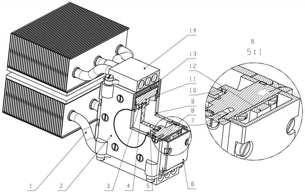
The invention discloses an ultra-narrow band optical filter temperature control configuration capable of accurately controlling temperature in a wide temperature range and an adjustment method thereof, and belongs to the field of airborne optical instruments. The ultra-narrow band optical filter is fixed in a cavity formed by the first sealing light window component, the main frame and the second sealing light window component through a pressing ring, an optical filter heat insulation pad is arranged between the ultra-narrow band optical filter and the step face of a through hole of the main frame, an optical filter positioning ring is arranged between the ultra-narrow band optical filter and the pressing ring, and it is guaranteed that the ultra-narrow band optical filter does not make contact with the main frame. The two thermoelectric refrigerators are respectively fixed on two opposite side walls of the main frame through the first heat sink component and the second heat sink component; and the two heating sheets are respectively fixed on the other two opposite side walls of the main frame through the two heating sheet fixing plates. The temperature of the ultra-narrow band optical filter is controlled through the main frame and the gas in the sealed optical window, the temperature of the ultra-narrow band optical filter is accurately controlled within the wide temperature range of-55 DEG C to 70 DEG C, and accurate and reliable temperature control of the ultra-narrow band optical filter within the airborne environment wide temperature range is achieved.

Description

technical field [0001] The invention belongs to the field of airborne optical instruments, and in particular relates to a temperature control configuration of an ultra-narrow-band optical filter with precise temperature control in a wide temperature range and an assembly method thereof. Background technique [0002] In long-range laser range finders, ultra-narrow-band filtering methods are often used to improve the background light suppression level of the echo optical signal received by the laser range finder system. The ultra-narrowband filter is a temperature-sensitive device, and the drift of the central wavelength with temperature will affect the transmittance. Therefore, in the wide temperature range of the airborne environment, it is necessary to design a package configuration for precise temperature control to ensure the emission and reception wavelength matching and the best transmittance. [0003] A temperature control configuration disclosed in the prior art is t...

Claims


Application Information

Patent Timeline
IPC IPC(8): G02B7/00
Inventor 任方宇崔伟黄晓婧郝培育李金全郭赛马文维李小明
Owner LUOYANG INST OF ELECTRO OPTICAL EQUIP OF AVIC
Learn More