Pressure monitoring device for water conservancy and hydropower engineering

A pressure monitoring, water conservancy and hydropower technology, applied in measuring devices, measuring fluid pressure, instruments, etc., can solve the problems of affecting the accuracy of measurement, large structural stress, easy to wear, etc., to achieve the effect of easy operation and use

Pending Publication Date: 2022-04-12
四川鑫圆建设集团有限公司
View PDF0 Cites 0 Cited by
  • Summary
  • Abstract
  • Description
  • Claims
  • Application Information

AI Technical Summary

Problems solved by technology

[0002] In the prior art, when measuring the underwater pressure, the measuring structure is subjected to the impact force of the water source due to the flow of the water source, which causes the fixed structure to be stressed and prone to wear, while the movable mechanism cannot accurately measure , which affects the accuracy of measurement and is not conducive to the monitoring of underwater pressure. Therefore, in view of the above problems, a pressure monitoring device for water conservancy and hydropower projects is proposed

Method used


Image

  • Pressure monitoring device for water conservancy and hydropower engineering
  • Pressure monitoring device for water conservancy and hydropower engineering
  • Pressure monitoring device for water conservancy and hydropower engineering

Examples


Embodiment 1

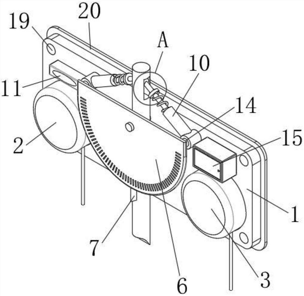
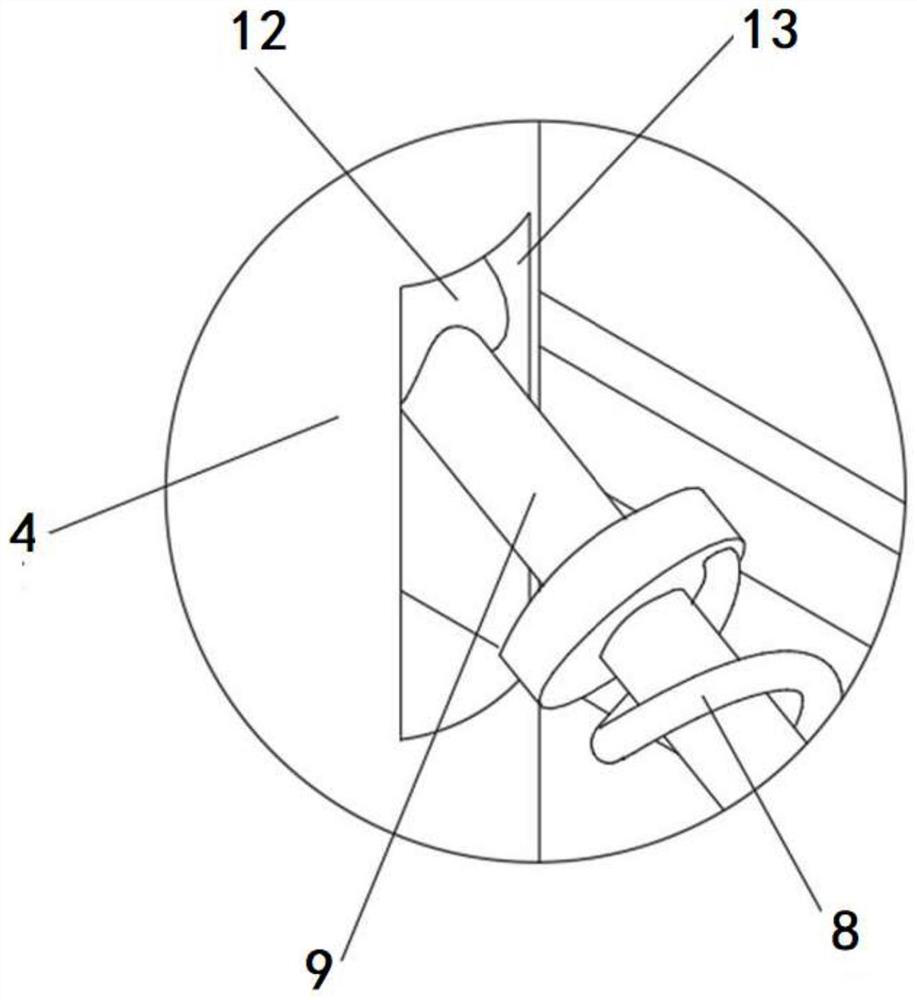
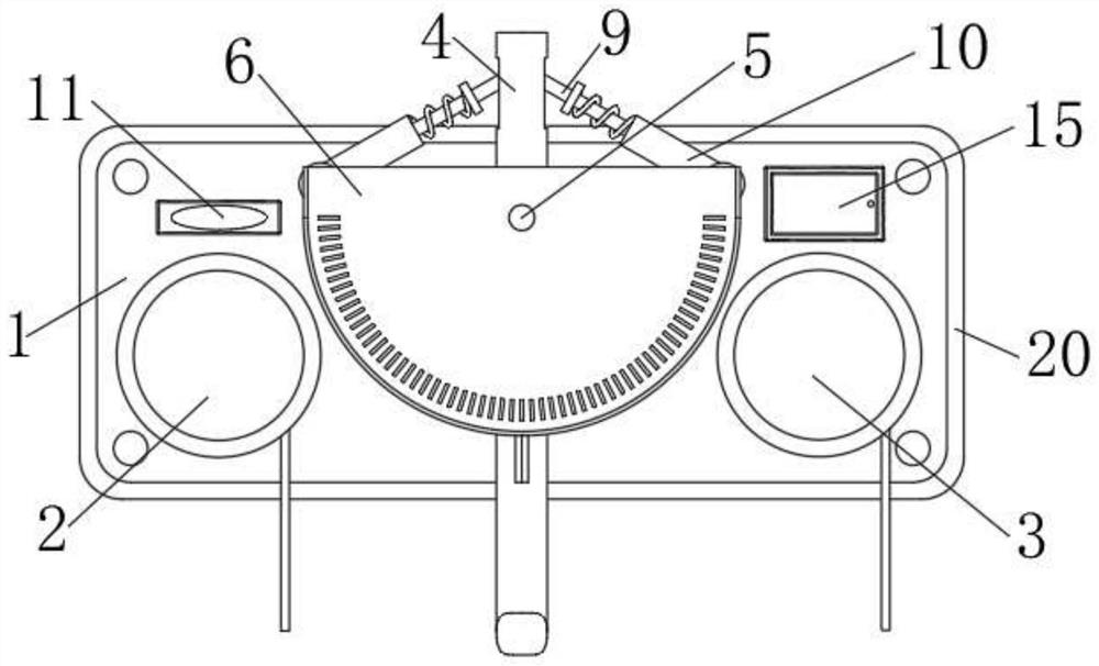
[0029] Such as Figure 1 to Figure 7 As shown, the pressure monitoring device for water conservancy projects provided by this embodiment includes a mounting plate 1, a wire structure 2, a water level alarm structure 3, a movable rod 4, a fixed shaft 5, a protractor 6, a pointer 7, a buffer spring 8, a slide Rod 9, sleeve 10, level bubble 11, slip ring 12, groove 13, fixing frame 14, control box 15, battery 16, PCB main control board 17, pressure sensor module 18, fixing hole 19 and rubber pad 20;

[0030] The mounting plate 1 is arranged in a rounded rectangular shape, four corners of the mounting plate 1 are provided with fixing holes 19, a control box 15 is installed on one end of the mounting plate 1, and a level bubble is installed on the other end of the mounting plate 1. 11. During actual installation, monitor the levelness of the installation board 1 through the level bubble 11, and then fix the installation board 1 on the wall through the expansion screw and the fixing...

Embodiment 2

[0037] The structure of the pressure monitoring device used in water conservancy and hydropower projects provided by this embodiment is basically the same as that of Embodiment 1, the only difference is that the wire structure 2 used in this embodiment is a spring wire, such as Figure 8 As shown, when the position of the pressure sensor module 18 is adjusted, the spring wire automatically expands and contracts, ensuring that the wire structure 2 is not disordered.


PUM


Abstract

The invention discloses a pressure monitoring device for water conservancy and hydropower engineering, and the device comprises a mounting plate, a wire structure, a water level alarm structure, a movable rod, a protractor, a spring buffer device, a control box, and a pressure sensor module. The movable rod and the protractor are mounted on the mounting plate through the fixing shaft, the pointer is mounted on the outer side of the movable rod below the protractor, the pressure sensor module is mounted at the bottom end of the movable rod, and the wire structure is electrically connected with the control box and mounted on one side of the pressure sensor module. The water level alarm structure is installed on one side of the protractor, one end of the spring buffer device is connected with the upper end of the movable rod, and the other end of the spring buffer device is connected to the installation plate. The movable rod of the pressure monitoring device can swing along with water flow, so that the device can be prevented from being impacted and damaged by the water flow, meanwhile, the position of the pressure sensor can be determined according to the swing angle of the movable rod, and underwater pressure monitoring is achieved.

Description

technical field [0001] The invention relates to the technical field of water conservancy and hydropower engineering, in particular to a pressure monitoring device used in water conservancy and hydropower engineering. Background technique [0002] In the prior art, when measuring the underwater pressure, the measuring structure is subjected to the impact force of the water source due to the flow of the water source, which causes the fixed structure to be stressed and prone to wear, while the movable mechanism cannot accurately measure , which affects the accuracy of measurement and is not conducive to the monitoring of underwater pressure. Therefore, in view of the above problems, a pressure monitoring device for water conservancy and hydropower projects is proposed. Contents of the invention [0003] The purpose of the present invention is to provide a pressure monitoring device used in water conservancy and hydropower projects, so as to solve the problems raised in the ab...

Claims


Application Information

Patent Timeline
Patent Type & Authority Applications(China)
IPC IPC(8): G01L19/06G01L19/12
Inventor 邹俊杰
Owner 四川鑫圆建设集团有限公司
Why Eureka
Try Eureka