


Quick Research
Generate reliable direction feasibility study reports for your R&D in just a few steps.

Technical Q&A
Discover and master advanced knowledge NOW. Basics, ideas, possibilities, all at once.

Find Solutions
As an expert in R&D theories, this can generate solutions to your technical problems instantly.

Evaluate Feasibility
Analyze your overall solution with one click, know your potential R&D risks in advance.

Monitor Landscape
Get weekly tech updates, stay abreast of the latest tech innovations and key insights.
Overhead conductor pay-off length measuring device
A technology for length measurement and overhead conductors. It is used in measurement devices, overhead line/cable equipment, instruments, etc. It can solve the problems of short circuit faults, prone to slippage, inconsistent conductor sag, etc., to achieve accurate length measurement and avoid slippage. Phenomenon, effect with a wide range of applications
- Summary
- Abstract
- Description
- Claims
- Application Information
AI Technical Summary
Problems solved by technology
Method used
Image

Examples
Embodiment 1
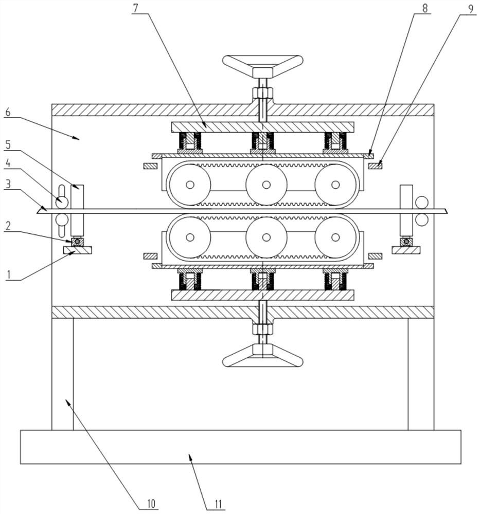
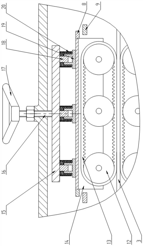
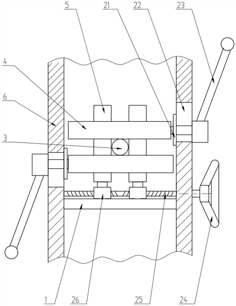
[0045] Such as Figure 1 to Figure 4 As shown, an overhead wire pay-off length measurement device includes a body frame 6 with a rectangular cross-section sheathed outside the wire 3 and a metering assembly 7 arranged in the body frame 6 near the middle. The metering assembly 7 is two groups symmetrically arranged on the upper and lower sides of the wire 3, and each group of metering assemblies 7 includes a support frame 14, three synchronous wheels 12 arranged axially along the wire 3, and crawler belts set on the synchronous wheel 12. 13 and an encoder 27 fixedly arranged on the support frame 14 for measuring the number of revolutions of the rightmost synchronous wheel 12.
[0046] The frame is connected to the body frame 6, the inner side of the crawler belt 13 is used for cooperating with the synchronous wheel 12, and the outer side of the crawler belt is lined with a wear-resistant layer, and the material of the wear-resistant layer is wear-resistant rubber. The speed is...
Embodiment 2
[0061] Such as Figure 5 to Figure 7 As shown, the difference between this embodiment and Embodiment 1 is that the body frame 6 includes an upper frame 29 with a door-shaped cross section and a U-shaped lower frame 28 with a U-shaped cross section. The horizontal plane where the axis of the wire 3 is located is symmetrical up and down, one side of the upper frame 29 is hinged to one side of the lower frame 28, and the other side of the upper frame 29 is detachably connected to the other side of the lower frame 28; The horizontal plane where the axis of the wire 3 is located is arranged symmetrically up and down.
[0062] Such as Figure 6 and Figure 7 As shown, the sliding seat 1, the second screw rod 25 and the second handwheel 24 are all arranged on the lower frame 28, and the two first guide rollers 4 are respectively connected on the upper frame 29 and the lower frame 28, and the lower frame 28 and the left side of the upper frame 29 are welded with laterally protrudin...
Embodiment 3
[0065] Such as Figure 8 and Figure 9 As shown, the difference between this embodiment and Embodiment 2 is that a sealed dust removal chamber 32 is provided on the left side of the metering assembly 7, and the dust removal chamber 32 is divided into mutually independent and upper frame 29 by the horizontal plane where the wire 3 is located. The upper dust removal chamber of welding and the lower dust removal chamber welded with lower frame 29.
[0066] Both the dust removal chamber and the lower dust removal chamber are provided with semicircular holes at the positions corresponding to the wires 3, the upper dust removal chamber and the lower dust removal chamber are fitted with the wire 3 in clearance, and the top of the dust removal chamber 32 is provided with a ventilation hole 35, so that The bottom of the lower dust removal chamber is welded with a dust removal pipe 34 communicating with the inside thereof, and the dust removal pipe 34 communicates with the negative pre...
PUM
 Abstract
Description
Claims
Application Information
 - R&D Engineer
- R&D Manager
- IP Professional
- Industry Leading Data Capabilities
- Powerful AI technology
- Patent DNA Extraction
Browse by: Latest US Patents, China's latest patents, Technical Efficacy Thesaurus, Application Domain, Technology Topic, Popular Technical Reports.
© 2024 PatSnap. All rights reserved.Legal|Privacy policy|Modern Slavery Act Transparency Statement|Sitemap|About US| Contact US: help@patsnap.com