A pipe detection device
A detection device and pipe material technology, which is applied in the direction of measuring devices, mechanical measuring devices, and mechanical devices, etc., can solve the problems of inconvenient use by manufacturers, low detection efficiency, high detection cost, etc., and achieve simple and clear operation, improve detection accuracy, and accurate sex high effect
- Summary
- Abstract
- Description
- Claims
- Application Information
AI Technical Summary
Problems solved by technology
Method used
Image
Examples
Embodiment 1
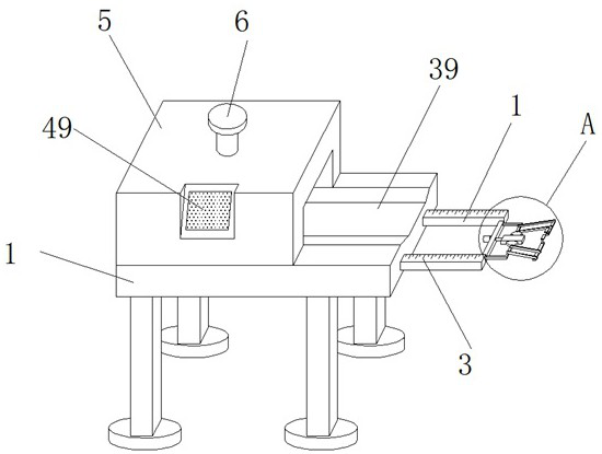
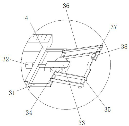
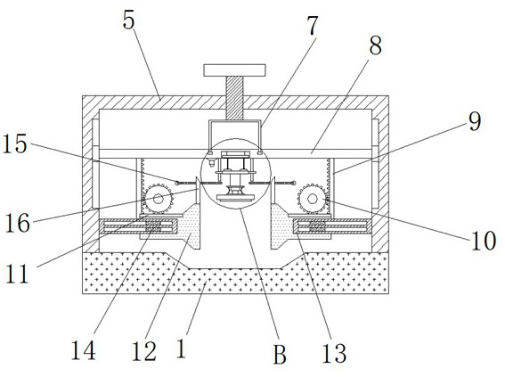
[0033] Such as Figure 1-5As shown, the pipe detection device according to the embodiment of the present invention includes a base 1, one side of the base 1 is provided with a symmetrically arranged slide bar 2, and the top of the slide bar 2 is provided with a scale 3, and the two groups of A connecting plate-4 is provided between the slide bars 2, a limit mechanism is provided on one side of the connecting plate-4, a box body 5 is provided on one side at the top of the base 1, and a box body 5 is provided on the top end of the box body 5. There is a threaded rod 6 extending to its inside, the bottom end of the threaded rod 6 is provided with a movable cylinder 7, and the bottom end of the movable cylinder 7 is provided with a connecting plate 2 8 that is movably connected with it, and the connecting plate 2 8 The bottom end is provided with locking mechanism, and described casing 5 is provided with the scale bar 15 that is arranged symmetrically, and one end of described sca...
Embodiment 2
[0035] Such as Figure 1-5 As shown, according to the pipe detection device according to the embodiment of the present invention, the locking mechanism includes a symmetrically arranged rack one 9 located at the bottom end of the connecting plate two 8, and one of the two sets of racks one 9 close to each other Each side is provided with a gear one 10 meshed with it, the bottom end of the gear one 10 is provided with a rack two 11 meshed with it, and the bottom end of the rack two 11 is provided with a gear connected to the measuring rod 16. Extrusion block 12, a pair of limit strips 13 are provided on both sides of the box body 5, and protrusions that are symmetrically arranged and slidably connected with the limit strips 13 are provided on both sides of the extrusion block 12. Block one 14, the specific structure of the locking mechanism can play a fixing effect on the pipe, ensure the stability and firmness of the pipe, and improve the measurement accuracy of the pipe.
Embodiment 3
[0037] Such as Figure 1-5 As shown, according to the pipe inspection device according to the embodiment of the present invention, the pressure measurement mechanism includes a symmetrically arranged limit rod 21 located at the bottom end of the connecting plate 2 8, and the limit rod 21 is sleeved with a matching The sliding sleeve of the two groups of sliding sleeves is provided with a fixed plate 22, and the top of the fixed plate 22 and the bottom end of one of the transmission wheels 19 are provided with some evenly distributed projections 23. The second bump 23 is provided with universal balls 24 that are movably connected with it. The universal balls 24 of the upper and lower groups are all connected by connecting rods 25. The bottom end of the fixed plate 22 is provided with a fixed column 26. The bottom end of the fixed column 26 is provided with a pair of vertically distributed reinforcement plates 27, and the two groups of reinforcement plates 27 are connected by sy...
PUM
 Abstract
Description
Claims
Application Information
 - R&D
- Intellectual Property
- Life Sciences
- Materials
- Tech Scout
- Unparalleled Data Quality
- Higher Quality Content
- 60% Fewer Hallucinations
Browse by: Latest US Patents, China's latest patents, Technical Efficacy Thesaurus, Application Domain, Technology Topic, Popular Technical Reports.
© 2025 PatSnap. All rights reserved.Legal|Privacy policy|Modern Slavery Act Transparency Statement|Sitemap|About US| Contact US: help@patsnap.com


